- Created: January–March 2016
- Materials: Brass, Maple, Acrylic
During my coterm year at Stanford I was fortunate to enroll in ME203, traditionally the capstone project class for students studying Mechanical Engineering. Students are exposed to basic manufacturing processes including milling, turning, casting, and welding, and are then directed to design and manufacture a product using those processes in the Stanford Product Realization Lab.
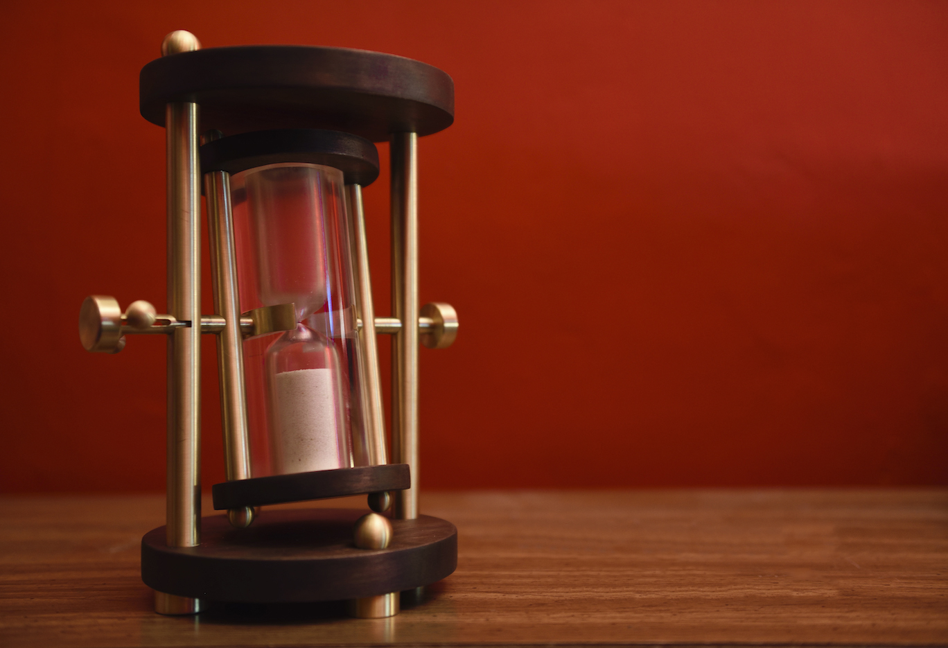
Projects completed by students in ME203 always look incredible, but, warned by friends who had taken the class previously, I knew they didn't always function very well. With that in mind, I didn't try to make a product that I actually wanted to use. I wanted to make something that I could show off, something that I could display proudly on a desk when I was old and say, "I made this". I wanted it to have an air of sophistication, and timelessness. I didn't want an accessory, but instead something that could stand on its own. I considered mathematical and scientific instruments such as a balance scale, an abacus, or a compass. Advances in technology have made primitive forms of these devices almost obsolete, but that doesn't diminish our respect for the purity of their function. I decided to build an hourglass.
Design & Prototyping
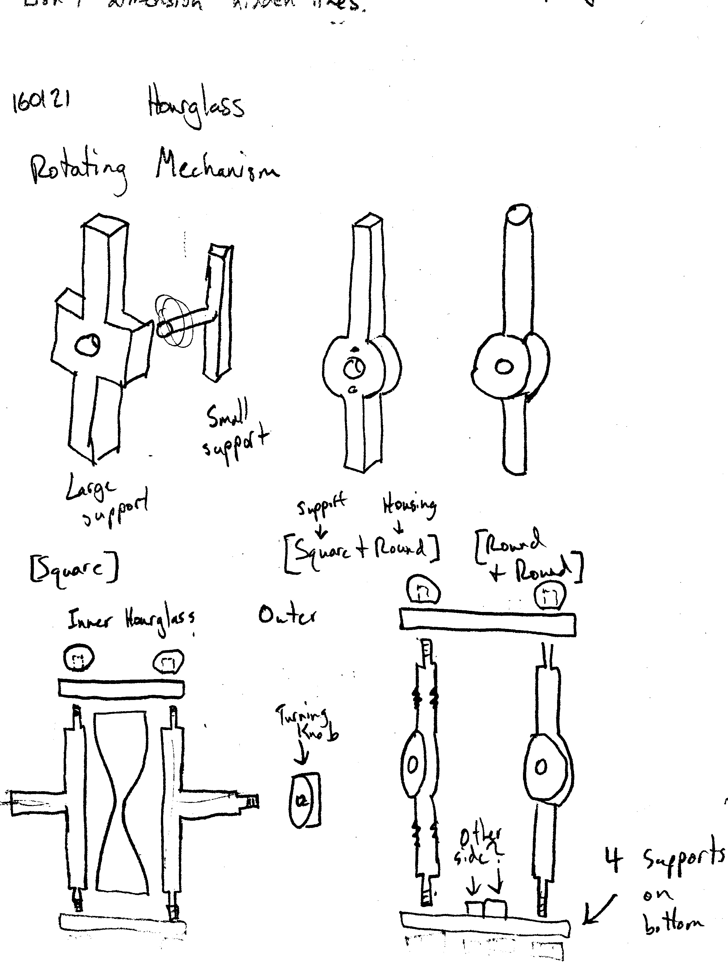
I had the idea of a rotating hourglass in my mind from the very beginning. I thought through a couple designs for how the inner hourglass could be mounted:
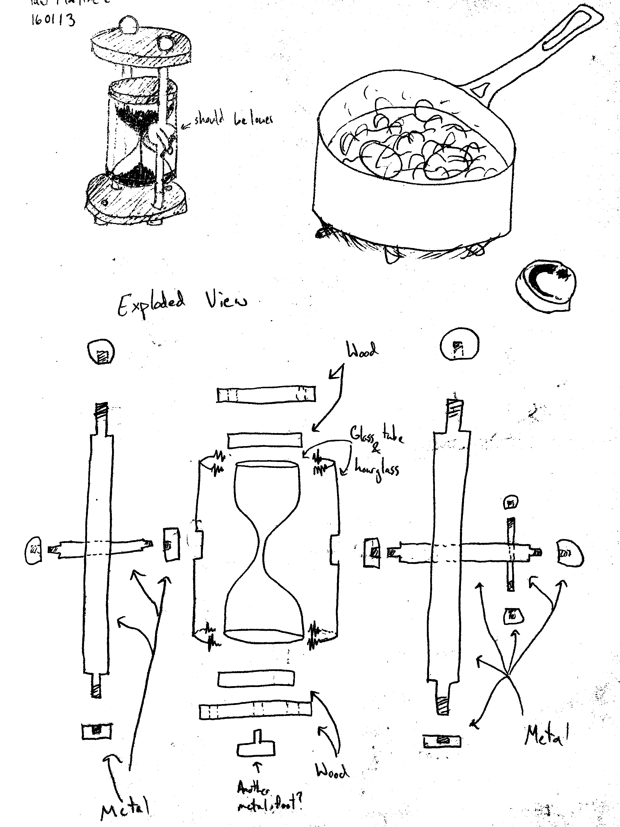
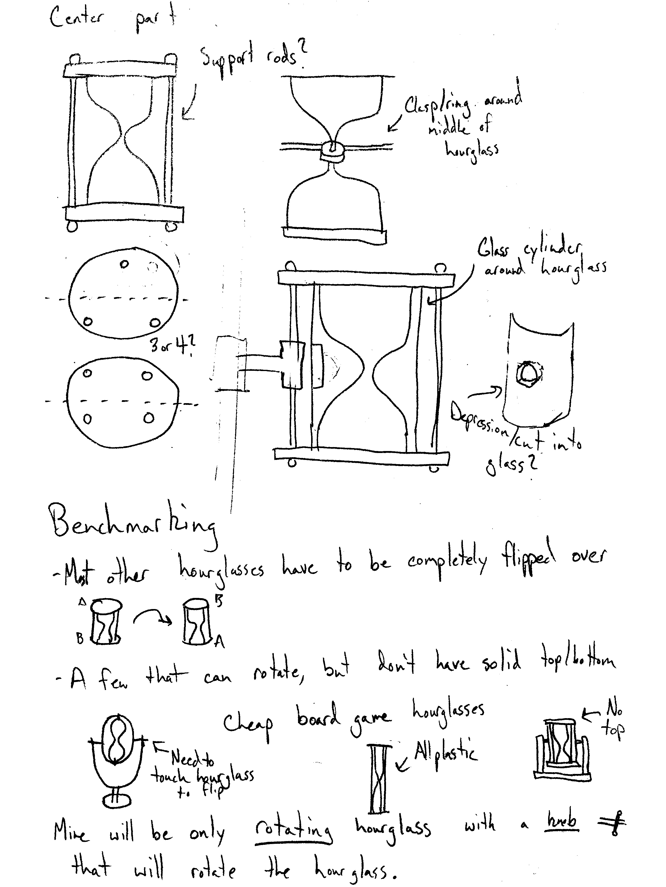
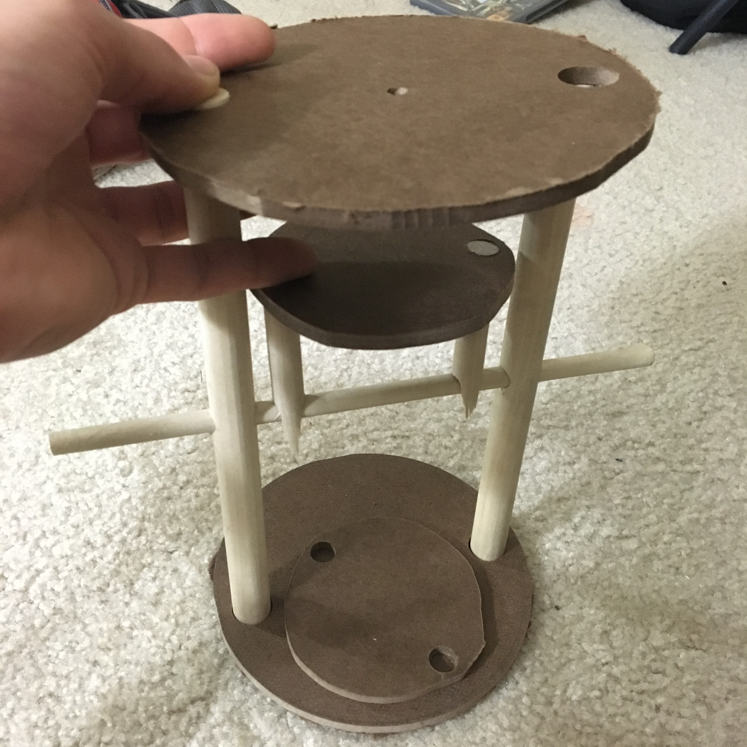
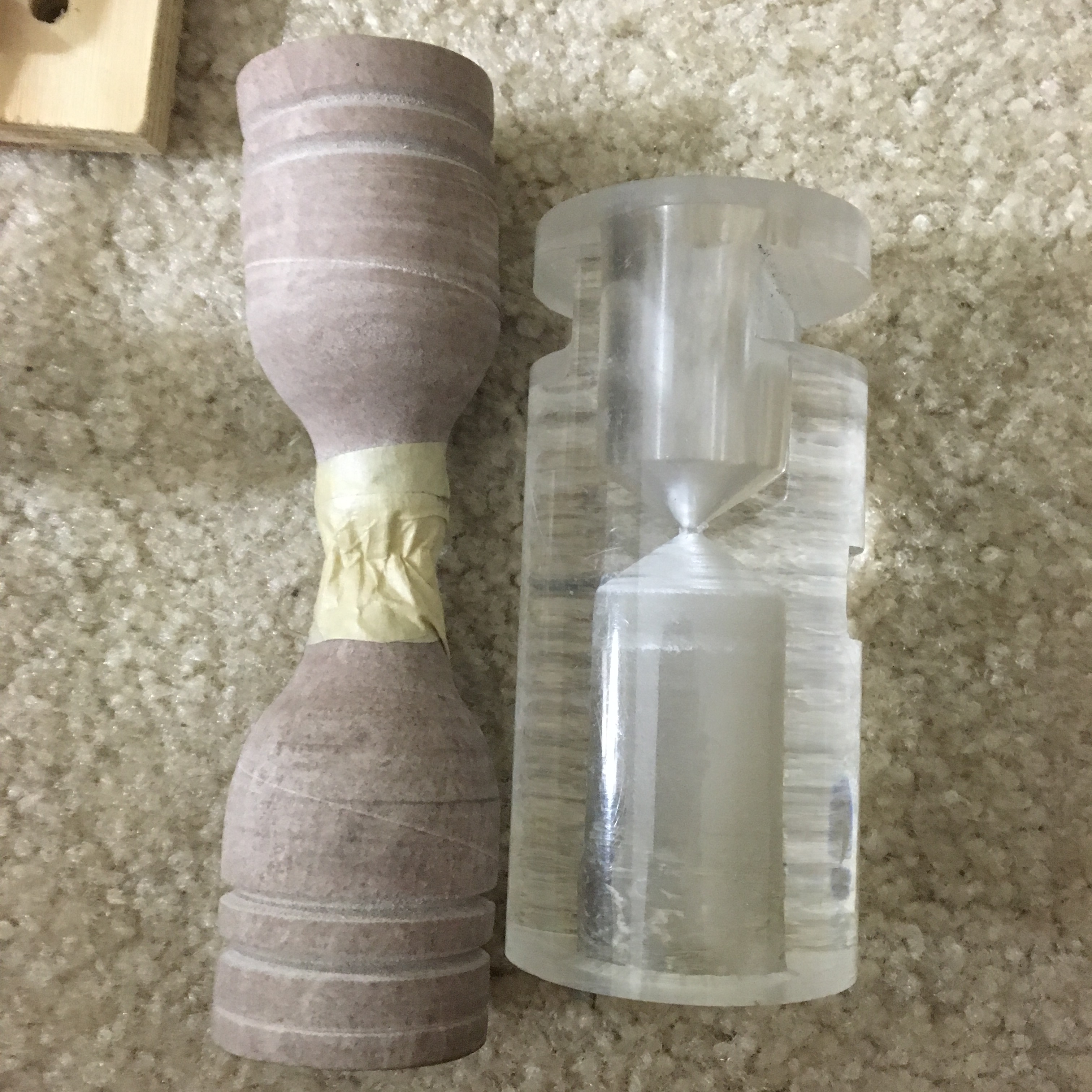
I settled on the dual-support design pretty early on. From there I moved on to basic structural prototypes:
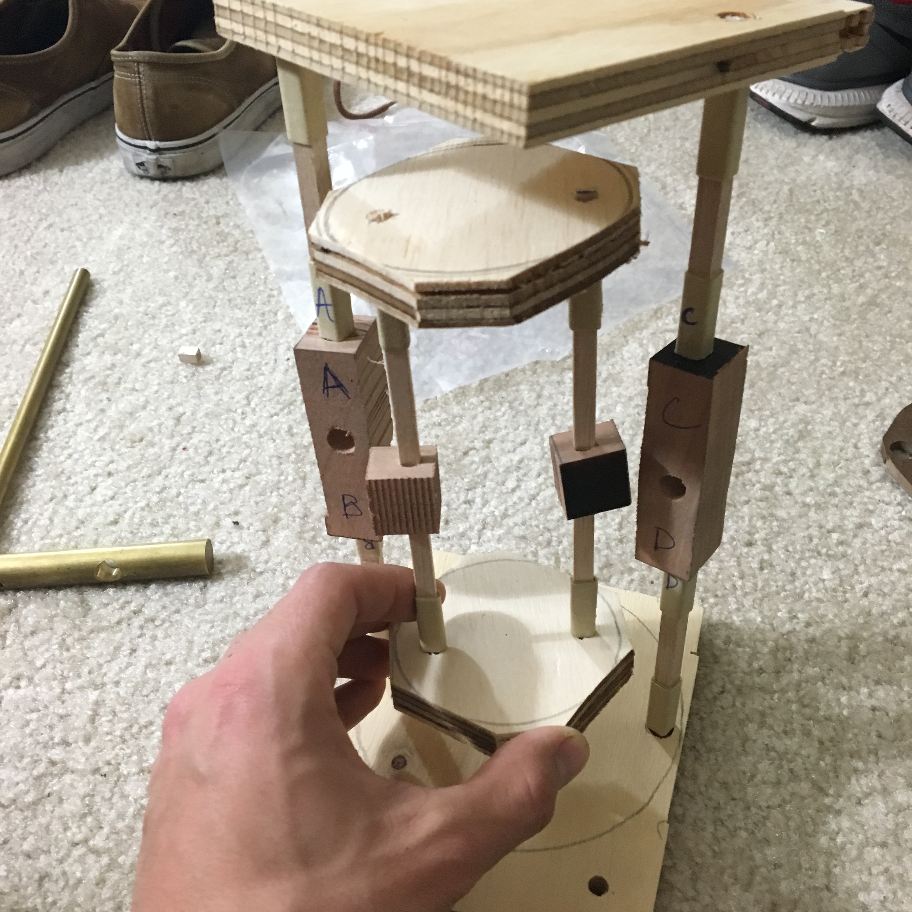
The inner part of the hourglass could swing freely. Immediately after flipping the hourglass all the sand would be in the top half, so the top would be heavier. I was worried that if it wasn't perfectly balanced it would want to flip back over, so I designed a locking mechanism that would prevent the inner part from rotating.
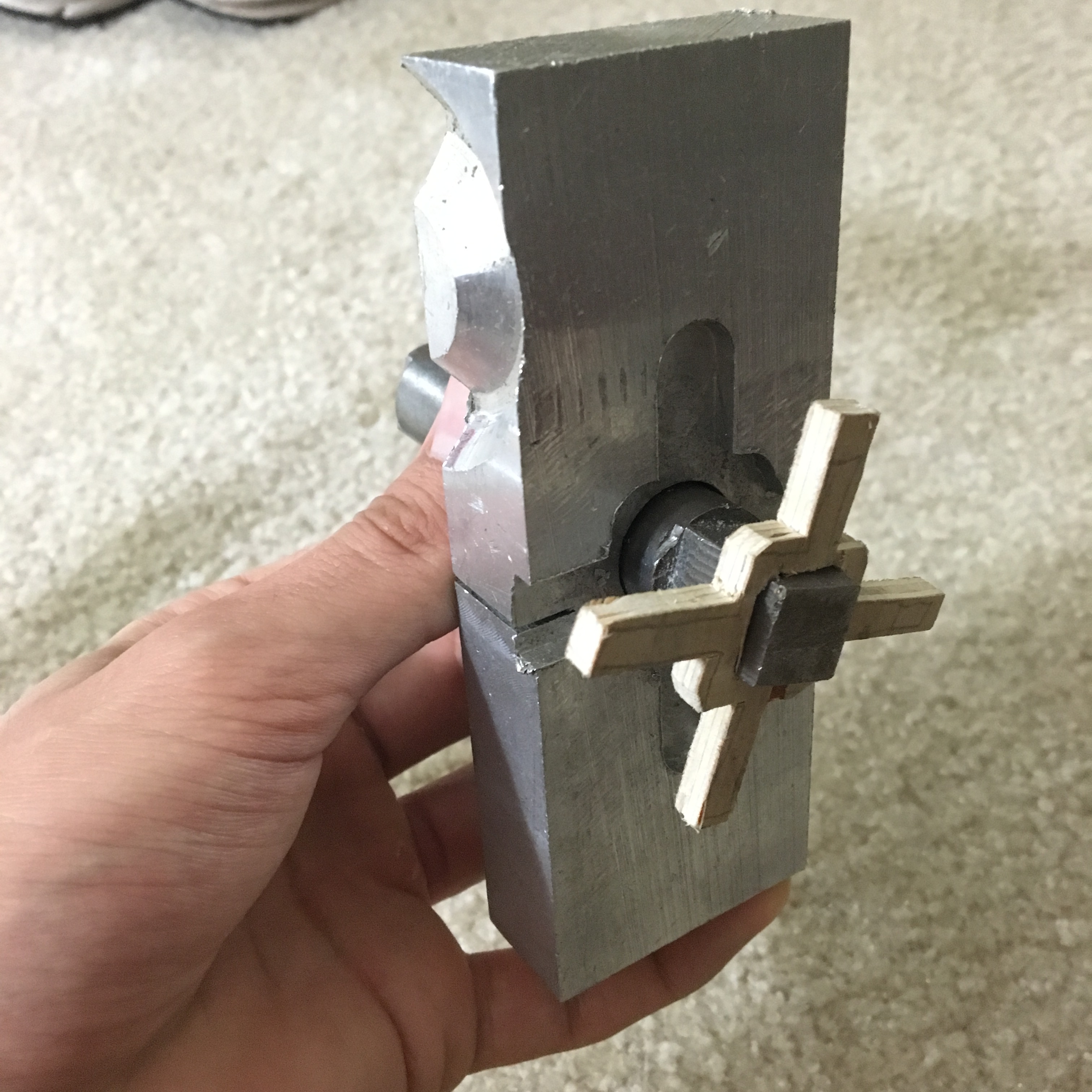
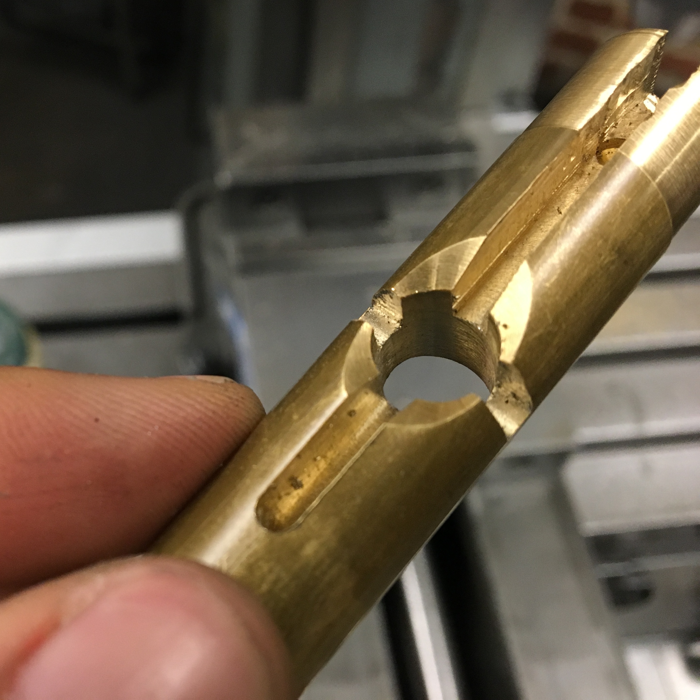
Originally I imagined a cross at the end of the axle, which could slide in and out of grooves along one of the outer supports. In order to provide torque on the axle, I originally thought part of the axle would have to be square, and the cross would sit around it (first picture below). However, this part would be difficult to machine, and it's not clear how I could machine an interior right angle.
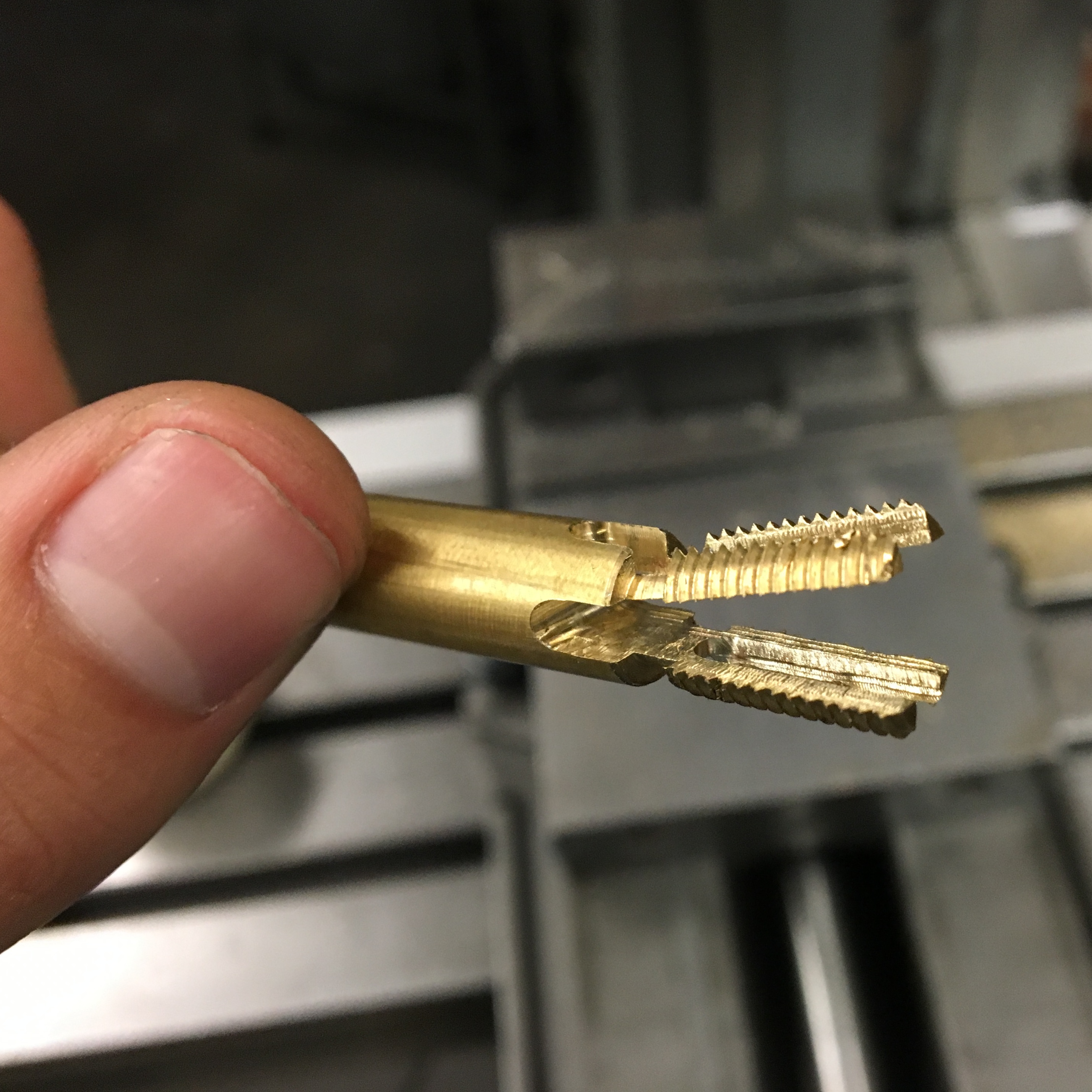
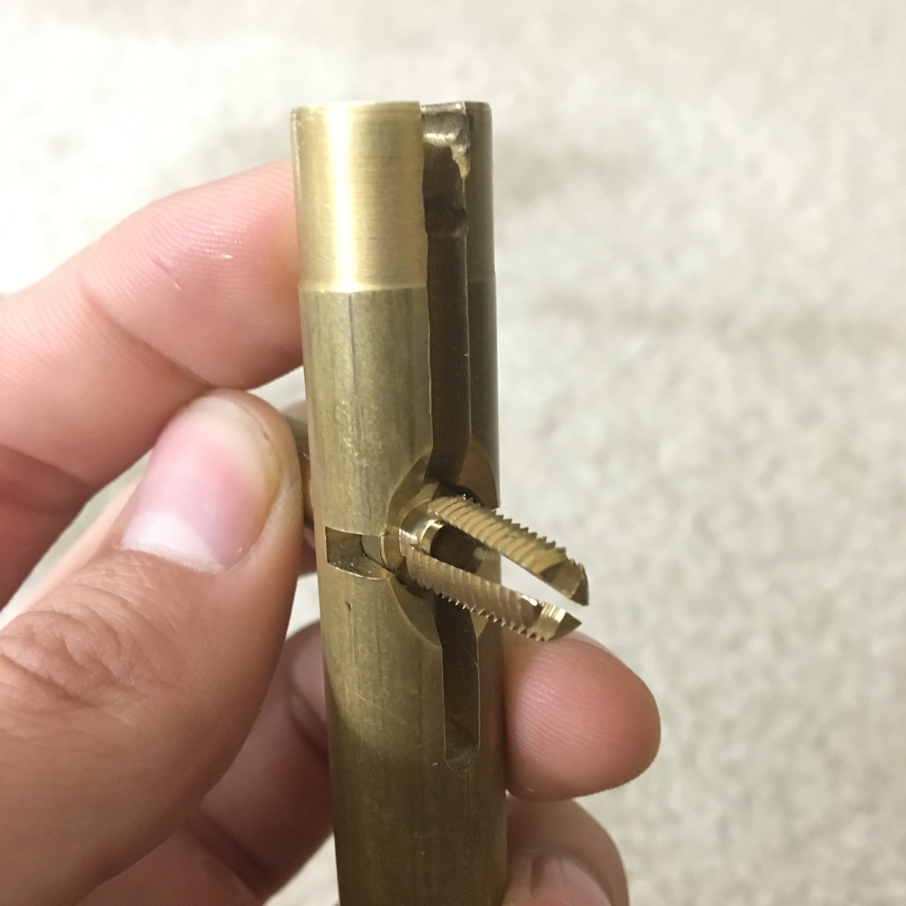
The next idea I explored was having the cross go through the axle. I would cut slits through the end of the axle, insert the cross, then screw a cap on the end. However, when I prototyped this idea the thin ends of the axle lacked structural integrity. Addititionally, when I explored creating the slot in the support, the vertical part of the slot didn't look right. I envisioned having round caps at the end of the cross, but that would require large insets at the top and bottom of the slot.
This exploration led me to abandon the cross idea and stick with a simple horizontal bar as the locking mechanism.
The most important of the hourglass is of course the glass itself! I considered purchasing one and simply enclosing it in rest of the structure, or somehow creating my own out of glass, but in the end I settled on acrylic that I would partially drill into from both sides. After an initial drill hole I would would use a chamfered end mill and a ball end mill to narrow the inner diameter to a point.
To mount the axle to the hourglass I would attach a circular segment to the end of the axle and have that fit into a groove in the acrylic. I explored what this would look like an a piece of scratch acrylic.
Eventually I made a full CAD model of the hourglass in SolidWorks. I loved this part; my model was fully parameterized, and I could modify any number of variables, such as the inner radius of the hourglass, the depth of the insets into the acrylic, or the width of the wood caps. It was also properly constrained so I could spin the inner part of the hourglass. I used this to ensure that the outer structure was tall enough to allow the inner part to spin all the way around (though the math is quite doable by hand).
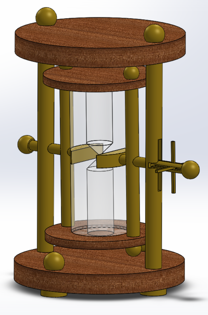
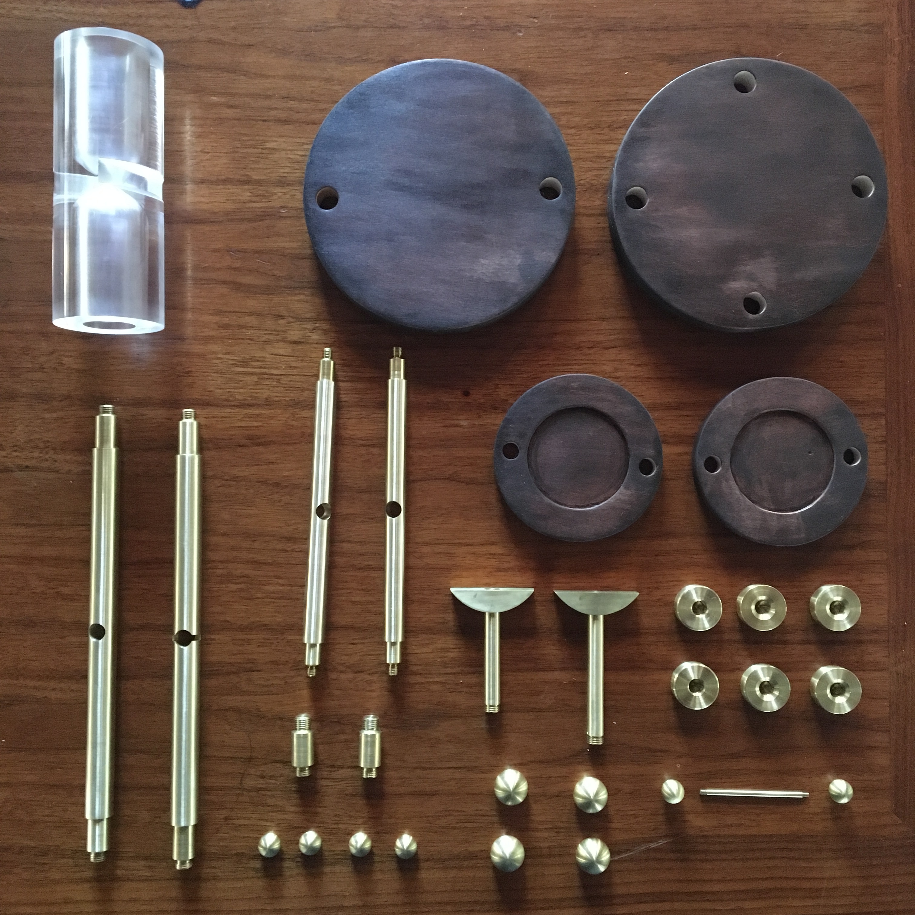
In total the design consisted of 32 different parts!
- Large wooden caps (2x)
- Large brass support
- Large brass support with notch
- Short off-axis brass supports (2x)
- Brass flat caps (4x for feet, 2x for end of axle)
- Large brass round caps (4x)
- Small wooden caps (2x)
- Small brass supports (2x)
- Small brass round caps (4x for inner structure, 2x for locking rod)
- Brass circular segment insets (2x)
- Brass axle piece
- Brass axle piece with notch
- Acrylic hourglass
- Brass locking rod
I considered making the outer structure just a bit too short, then carving out a smooth crater on the inside of the top and bottom caps. This would create a cool illusion when viewing the hourglass from the side and spinning it, because it would look like the two parts should be colliding. But I wasn't sure how I could precisely carve out the craters, and this part of the design remained a cool "What if...?"
Machining
There were five major groups of pieces that I needed to machine: supports, end caps, the brass insets, hourglass itself and the wooden tops.
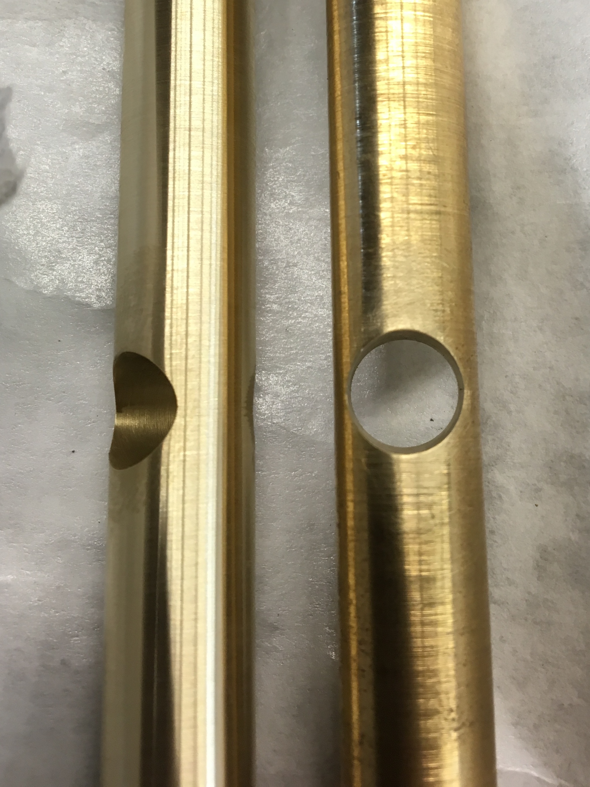
Supports and Axle
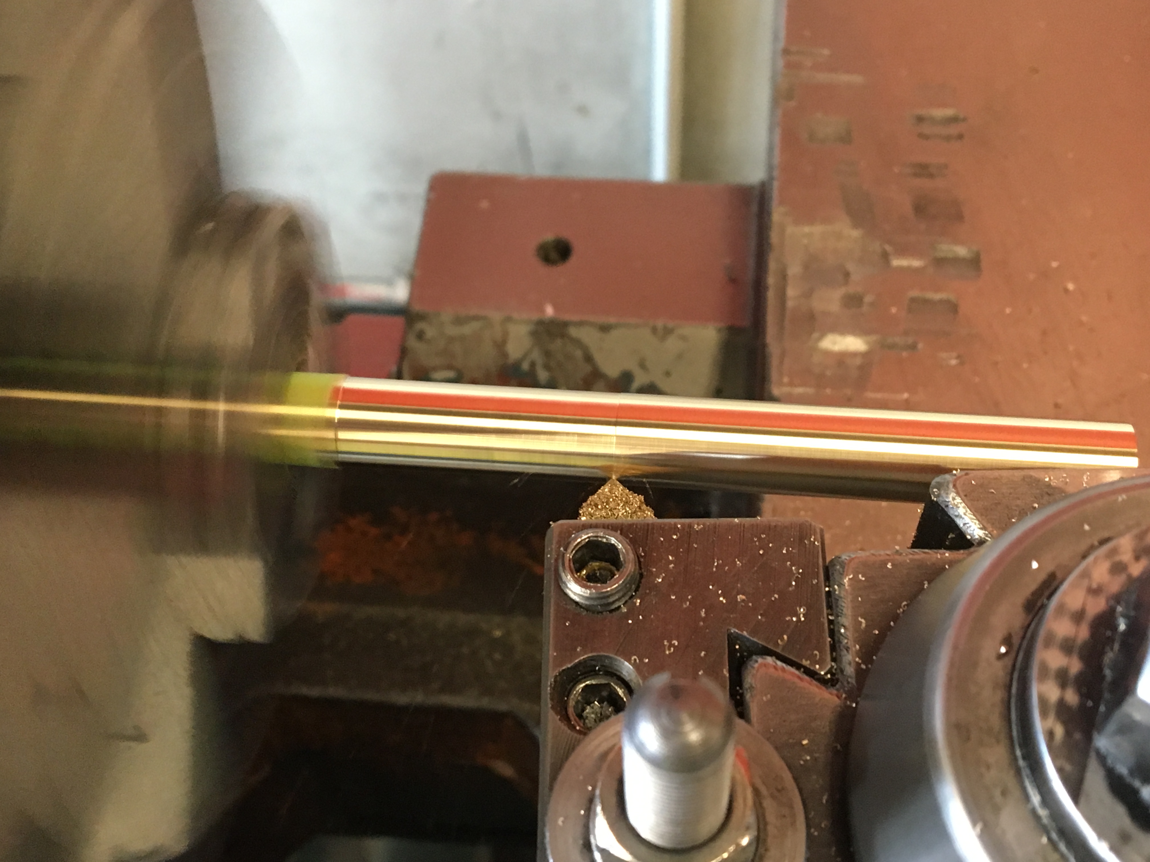
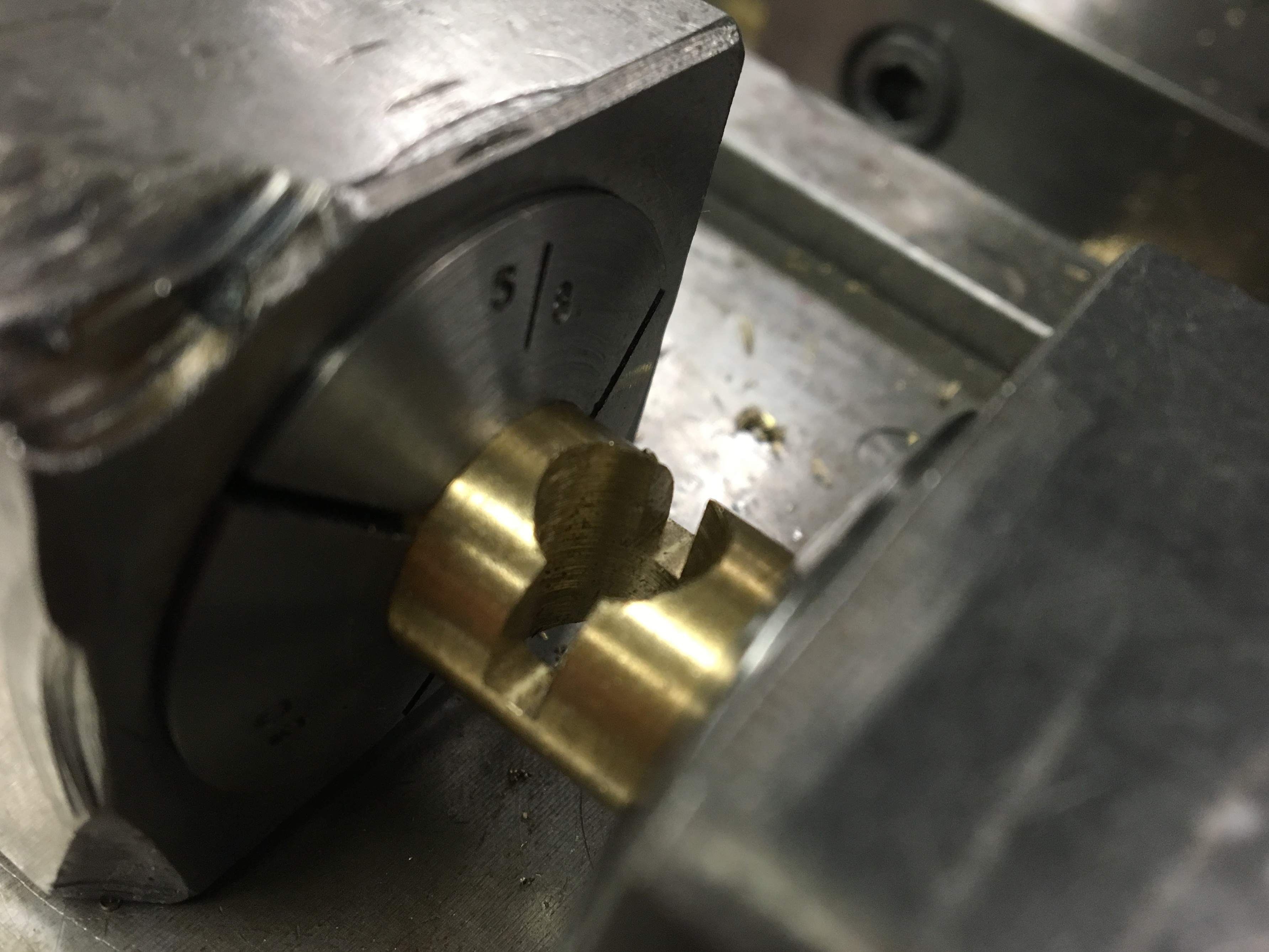
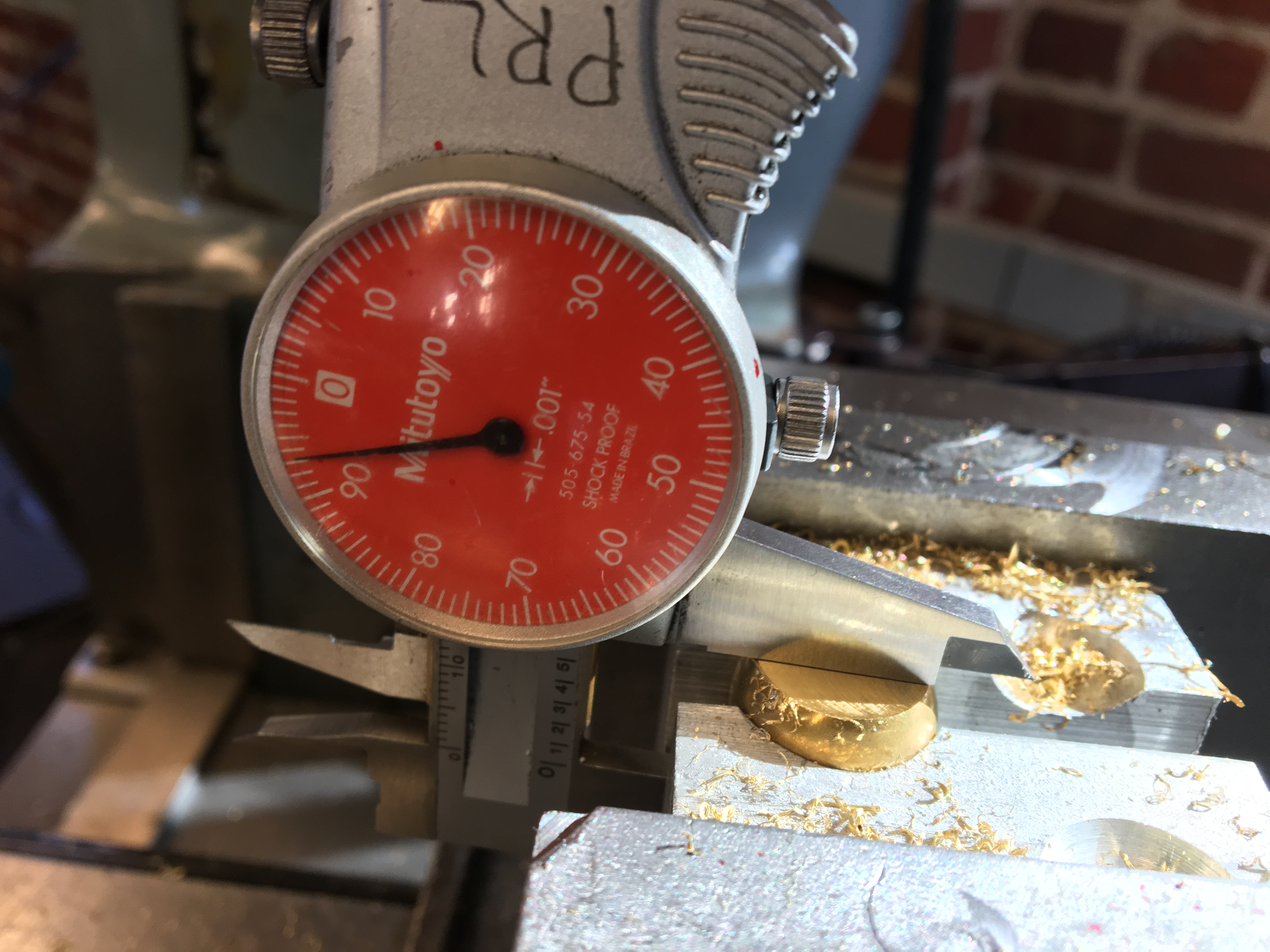
The supports and axle were't terribly complicated to machine. The outside diameter of the supports didn't need to meet a precise specification, so I started with 5/8" and 1/2" diameter brass rod stock and simply did a finishing pass. And for the short invisible supports for the off-axis feet I simply started with the 1/2" as well. The axle, however, did require a precise diameter, because it is part of both a press fit into the segment insets, and a clearance fit through the supports. Therefore, the axle was also turned down from a 1/2" rod, rather than using a 3/8" rod from the start.
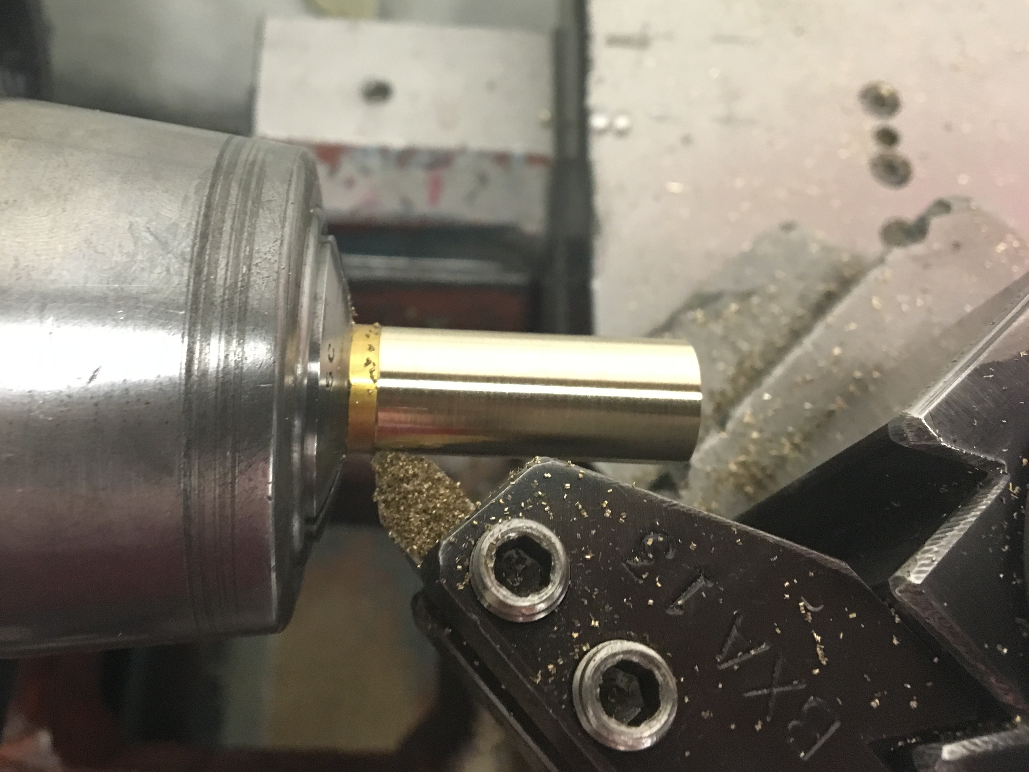
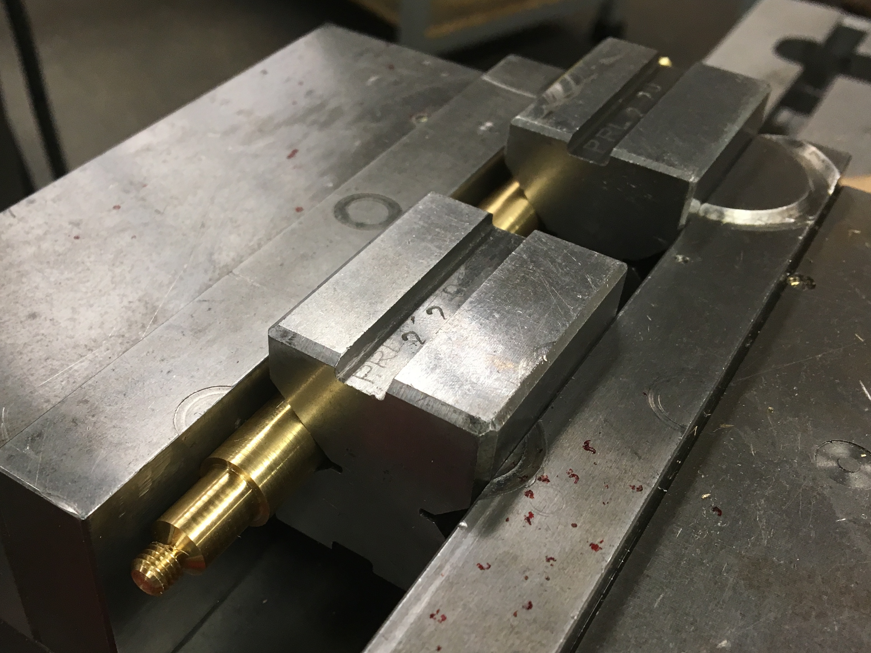
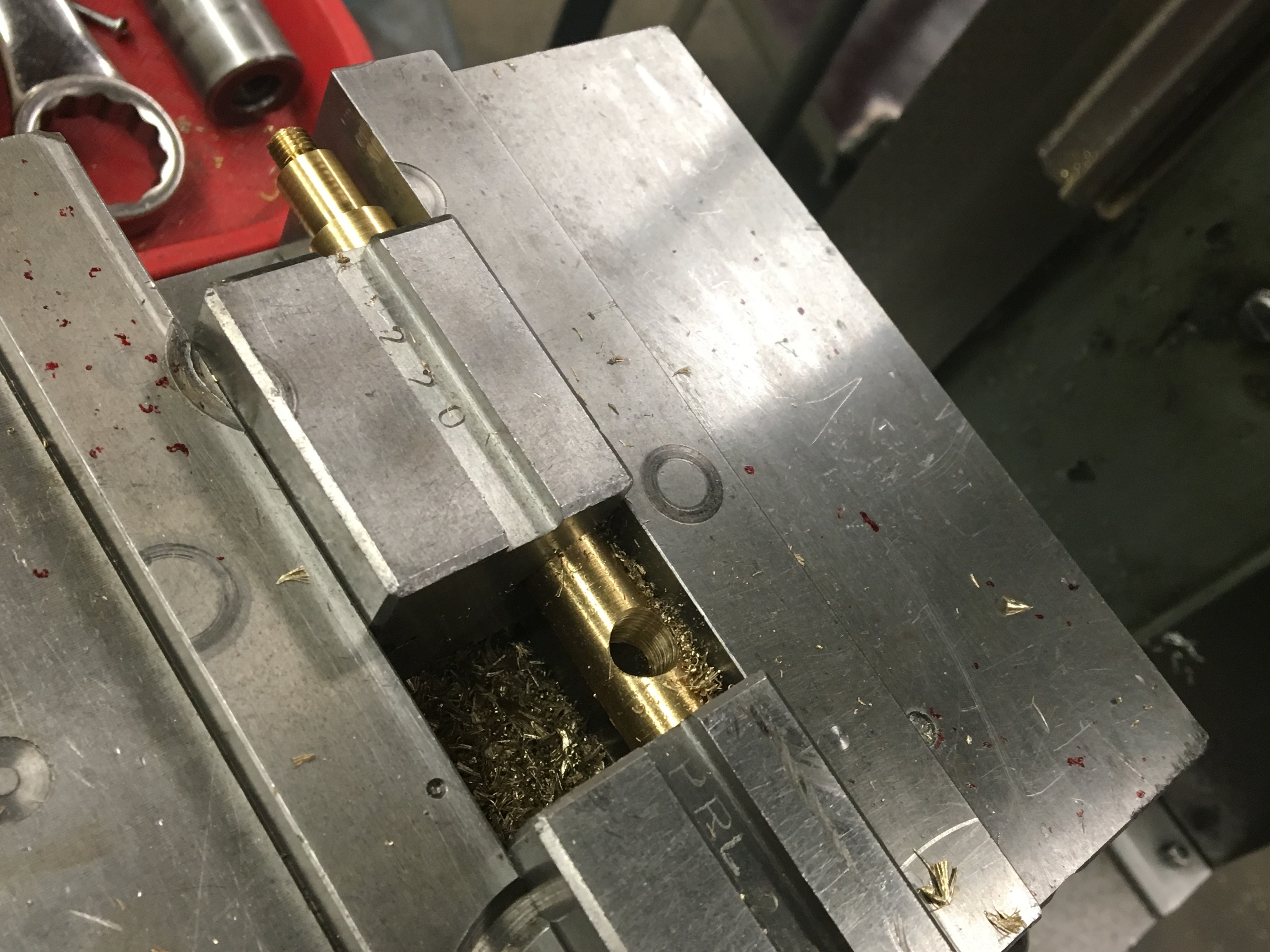
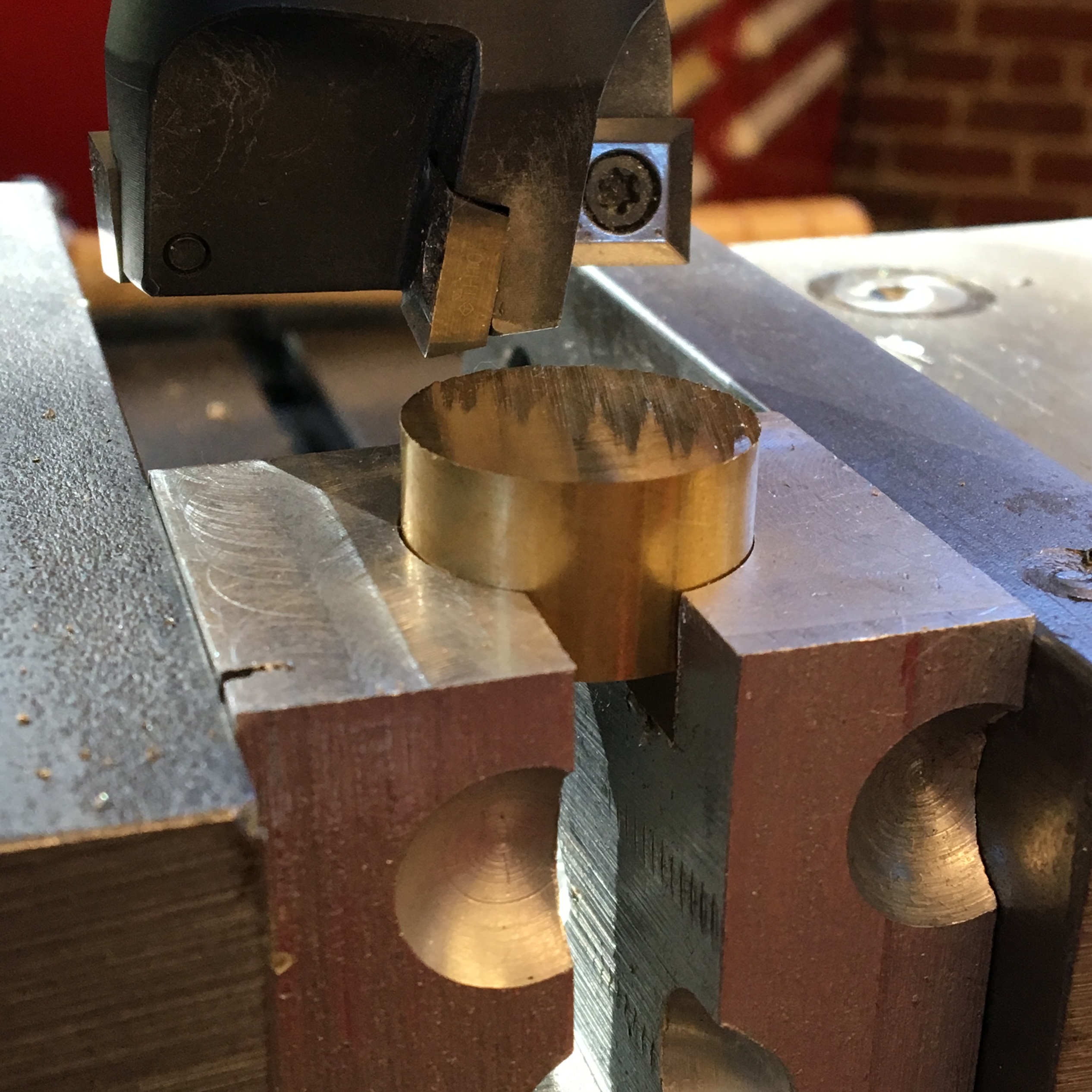
While the ends of the rods were simple to machine, it was tricky to figure out how to fixture them in a way that exposed the ends so they could be used for edge-finding to ensure the hole was drilled in the exact center of the support. I was able to put the large supports in two collet blocks, which left just enough room to drill the axle hole and mill the locking slot, and also allowed access to the ends with the edge-finder.
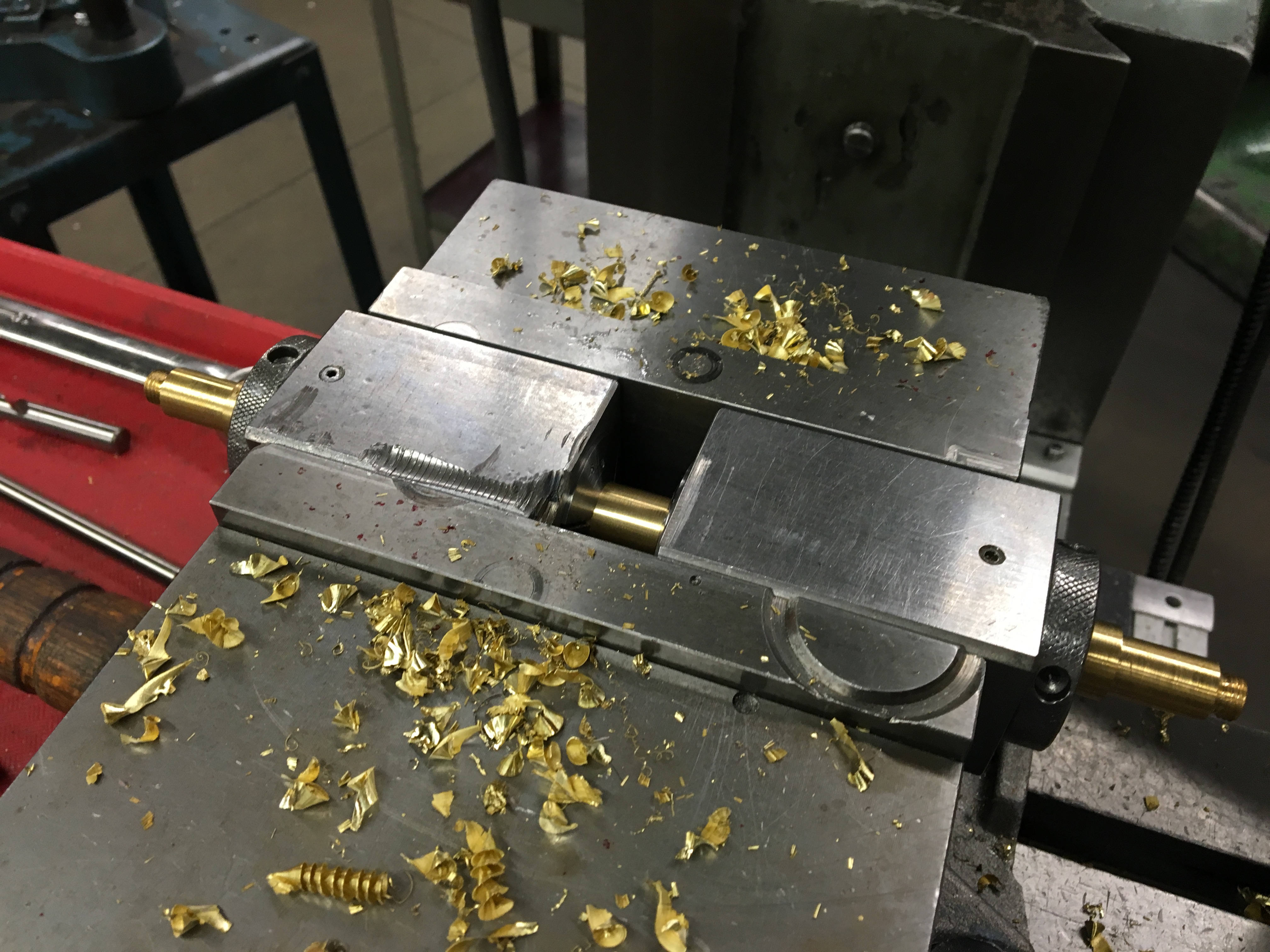
For the smaller supports however, the collet blocks were too big; they have covered up the ends of the support, so I would have been able to use and edge finder to find the center of the support. For these I used V-blocks instead:
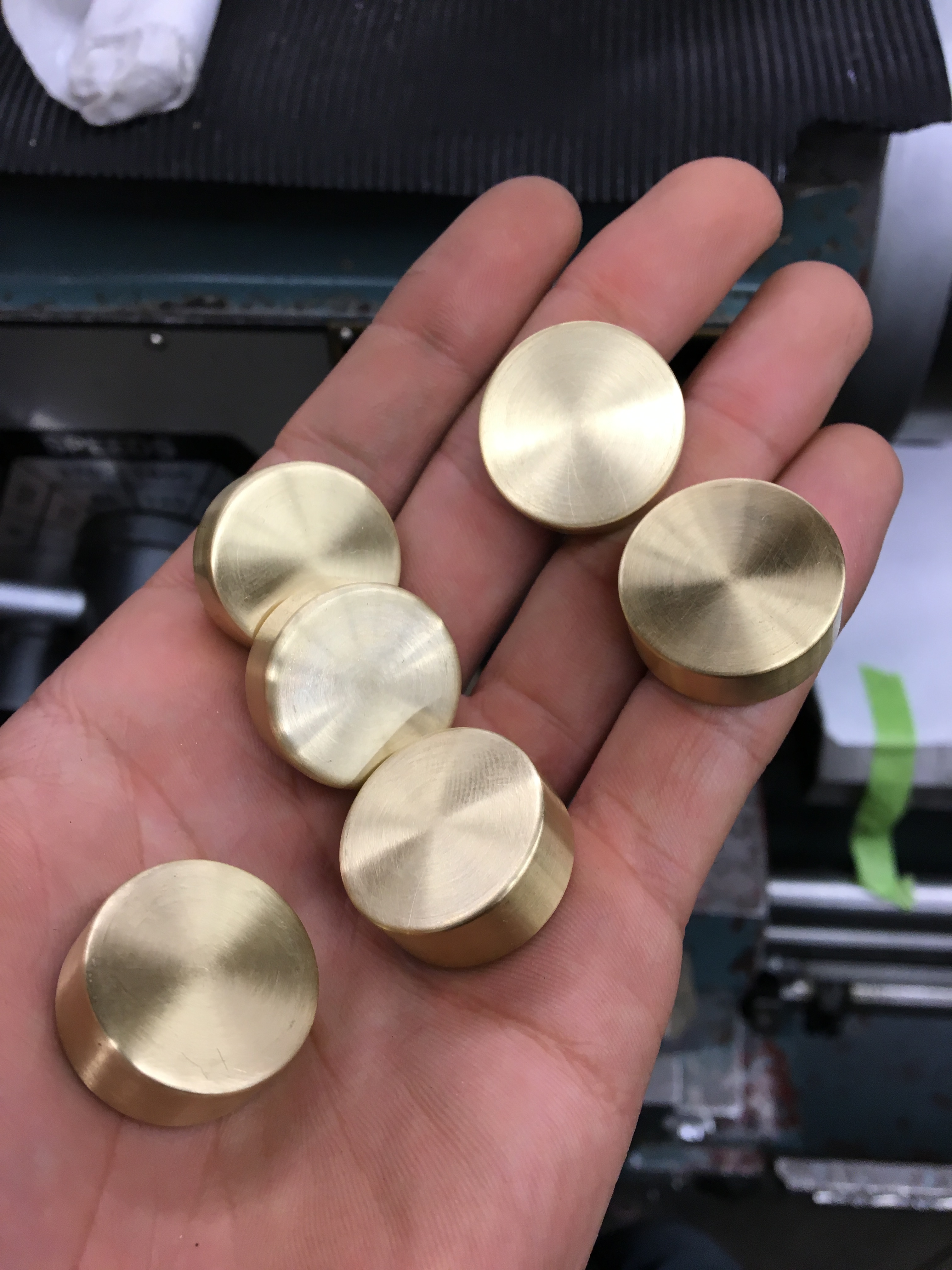
Brass End Caps
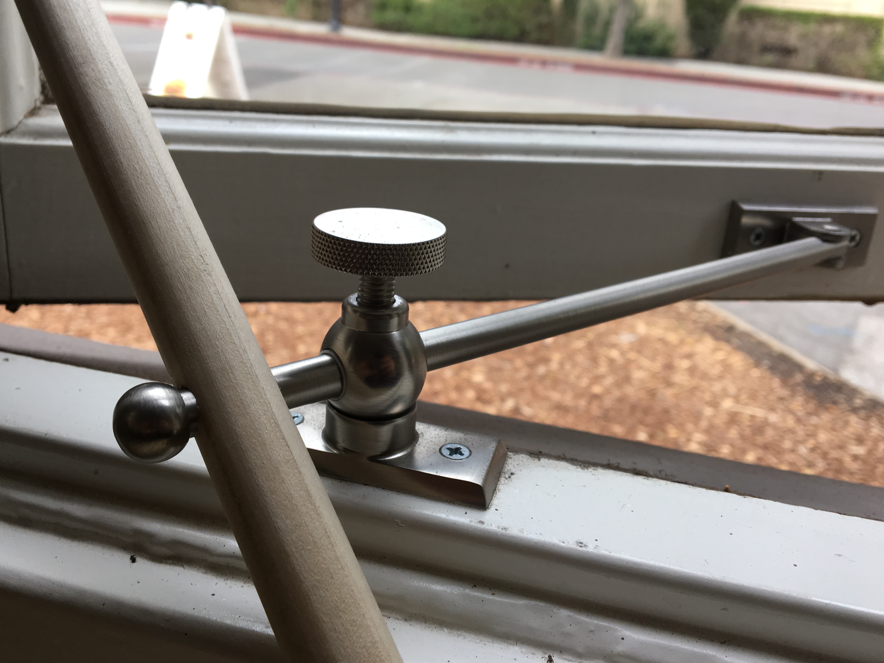
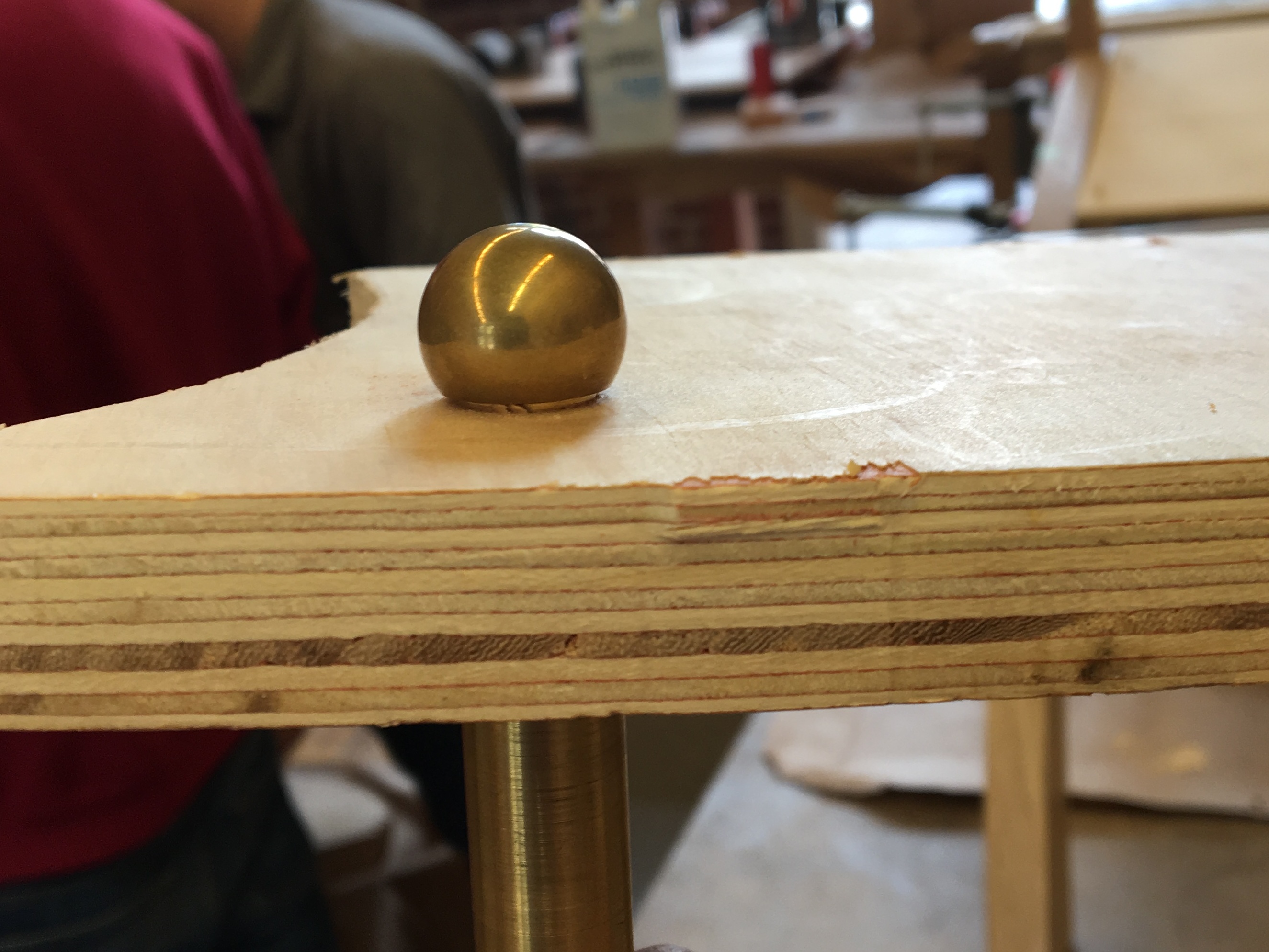
Spherical brass end caps were part of my design from my very first sketch. I found inspiration for the exact technical design from a window opening mechanism in Old Union, the building next to the PRL.
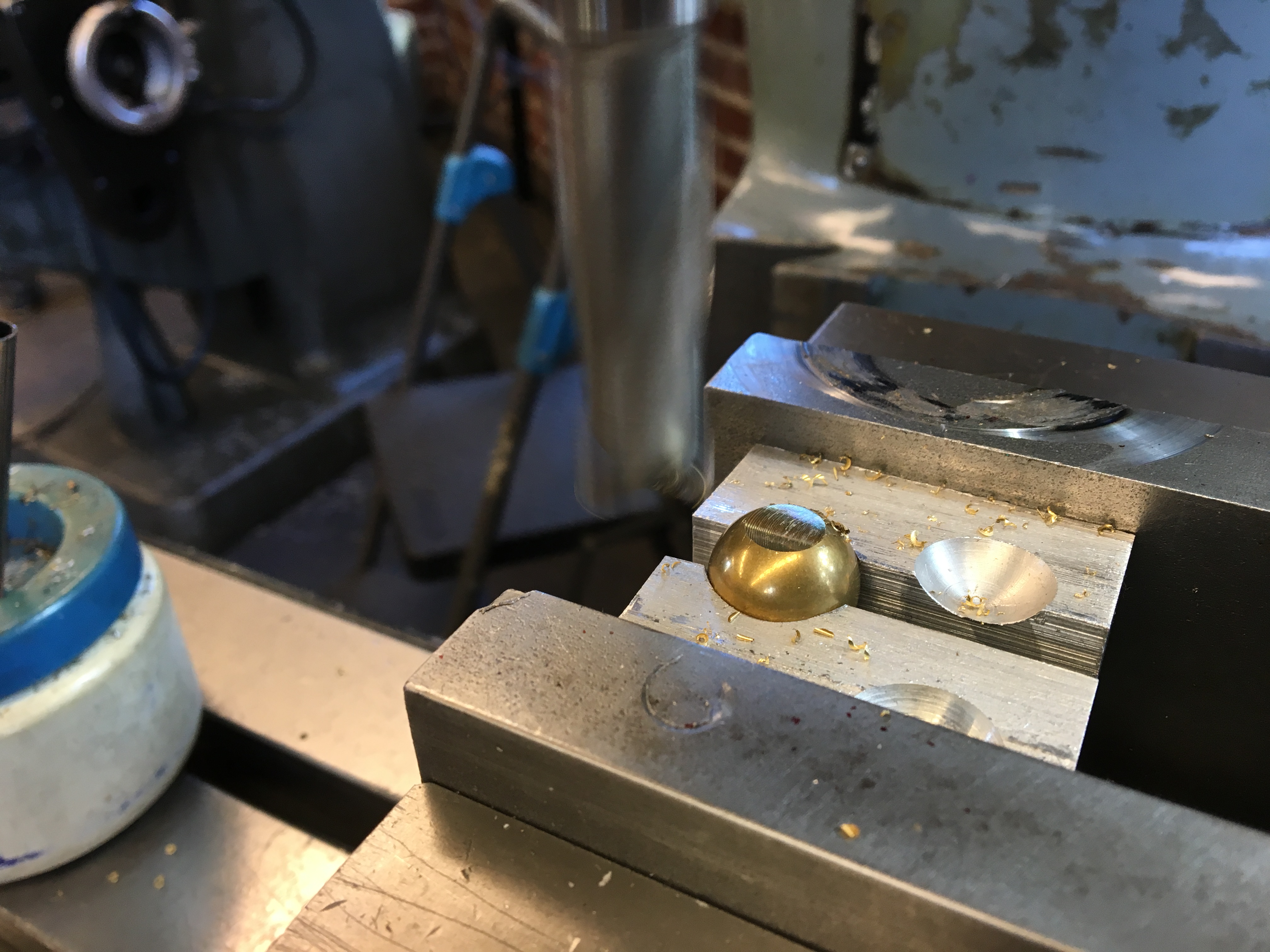
I ordered 3/4" and 1/2" diameter brass balls from McMaster-Carr, and then had to figure out how to machine them. I created soft jaws by cutting into some scrap pieces of aluminum with ball end mills... but I didn't really think it all the way through the first time. I needed to "drill" into the scrap pieces from the side, not from above.
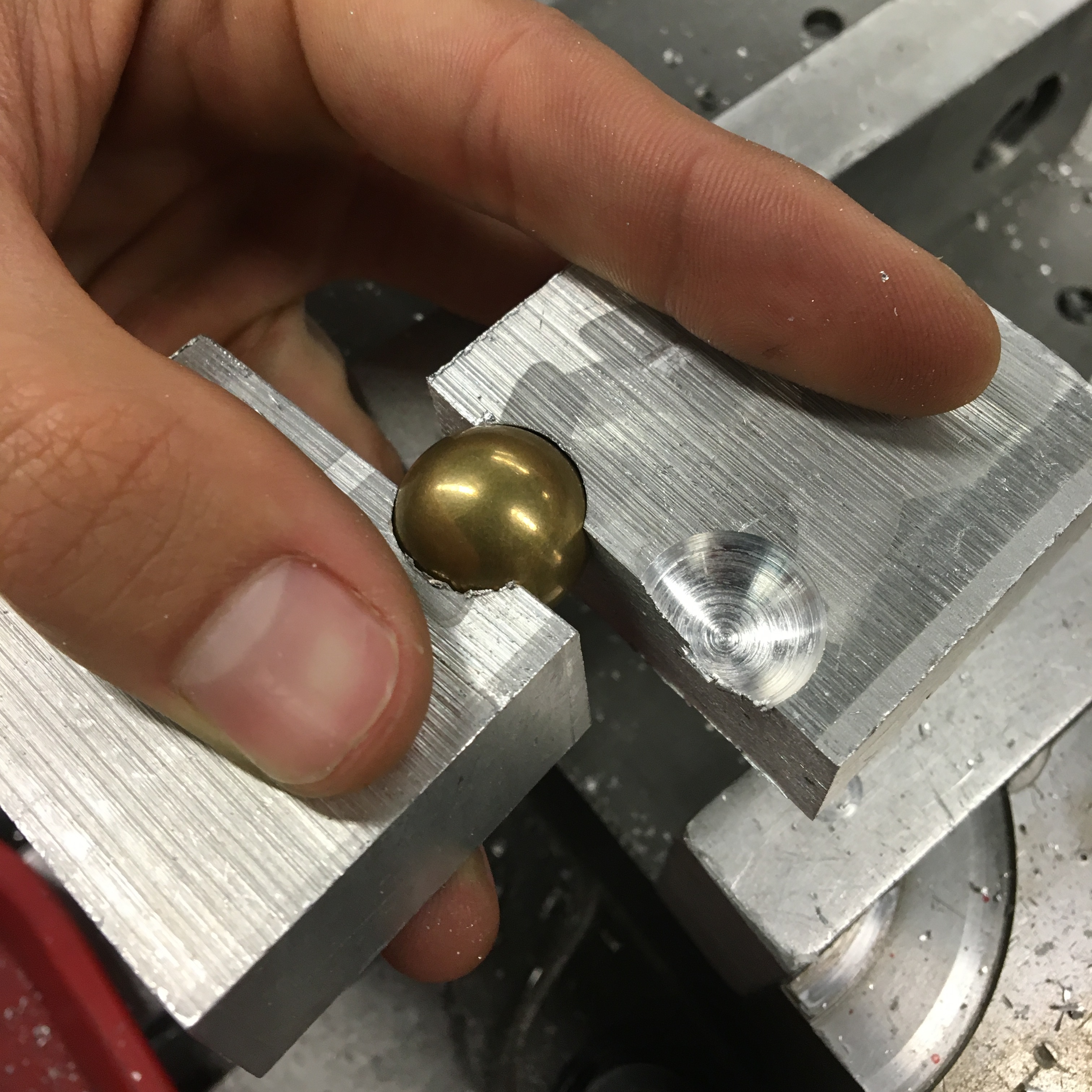
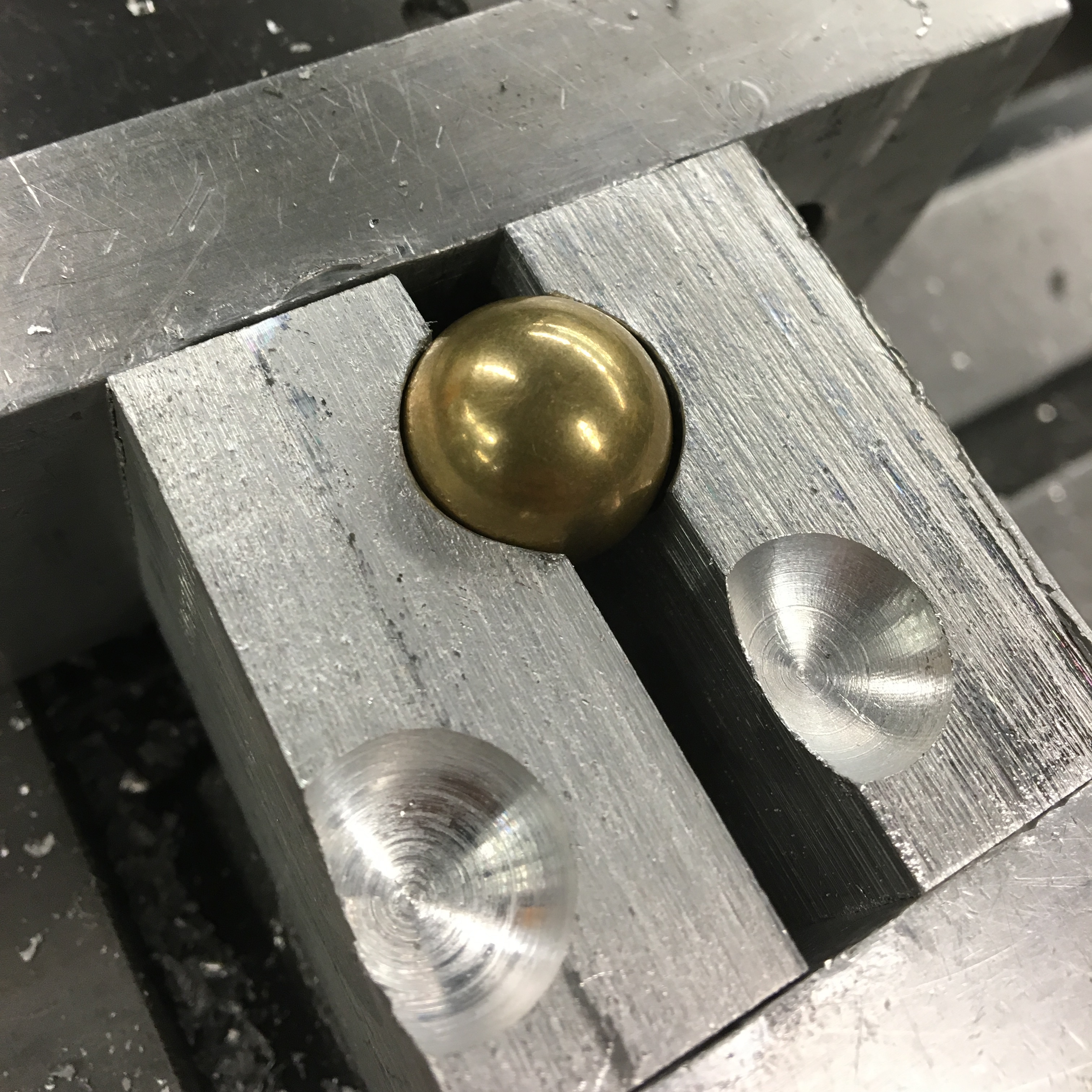
The second picture above still shows incorrect fixturing! As shown, the clamps only apply force to the soft jaws. The cavity drilled out by ball end mill functions as a "cage" for the brass balls, so it can't fly away when being machined. But there aren't actually any competing forces keeping the ball in place, and the fit isn't perfect, so the ball would rattle around as soon as a tool started cutting into it. The soft jaws should be rotated by 90 degrees so that the forces are applied through the soft jaws to the ball. Subsequent pictures show the correct orientation.
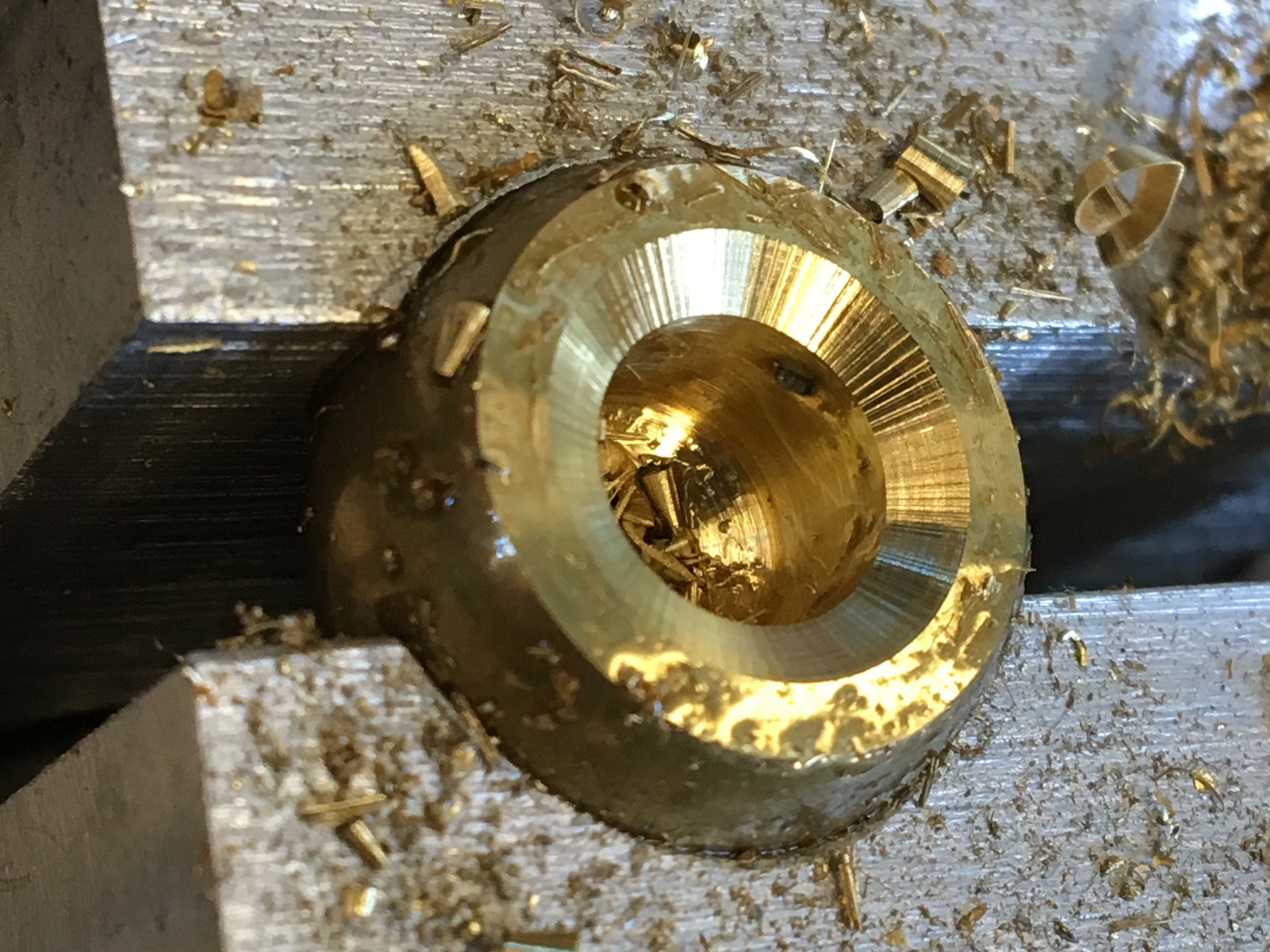
Actually machining each brass ball required many steps and a bunch of different tools I put into the manual mill:
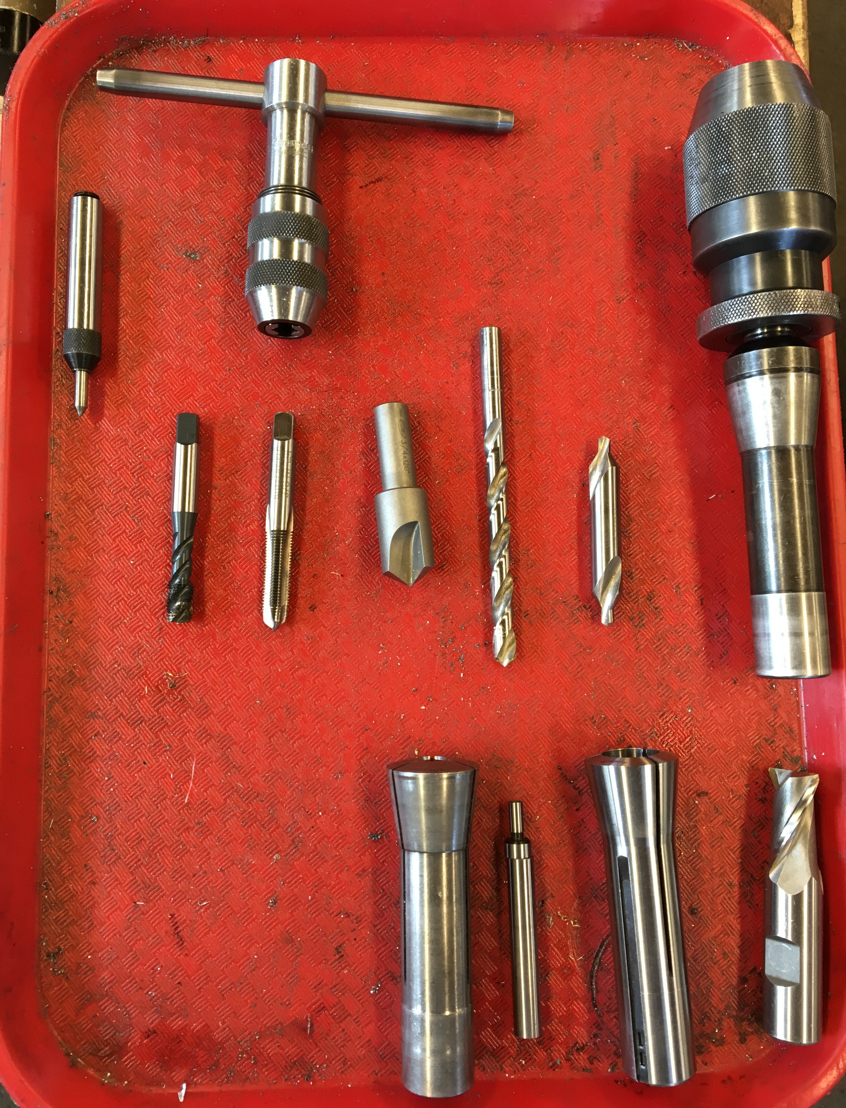
- Collet chuck
- Two sizes of collets
- Edge finder for centering
- Square end mill
- Centering drill bit
- Regular drill bit
- Countersink drill bit
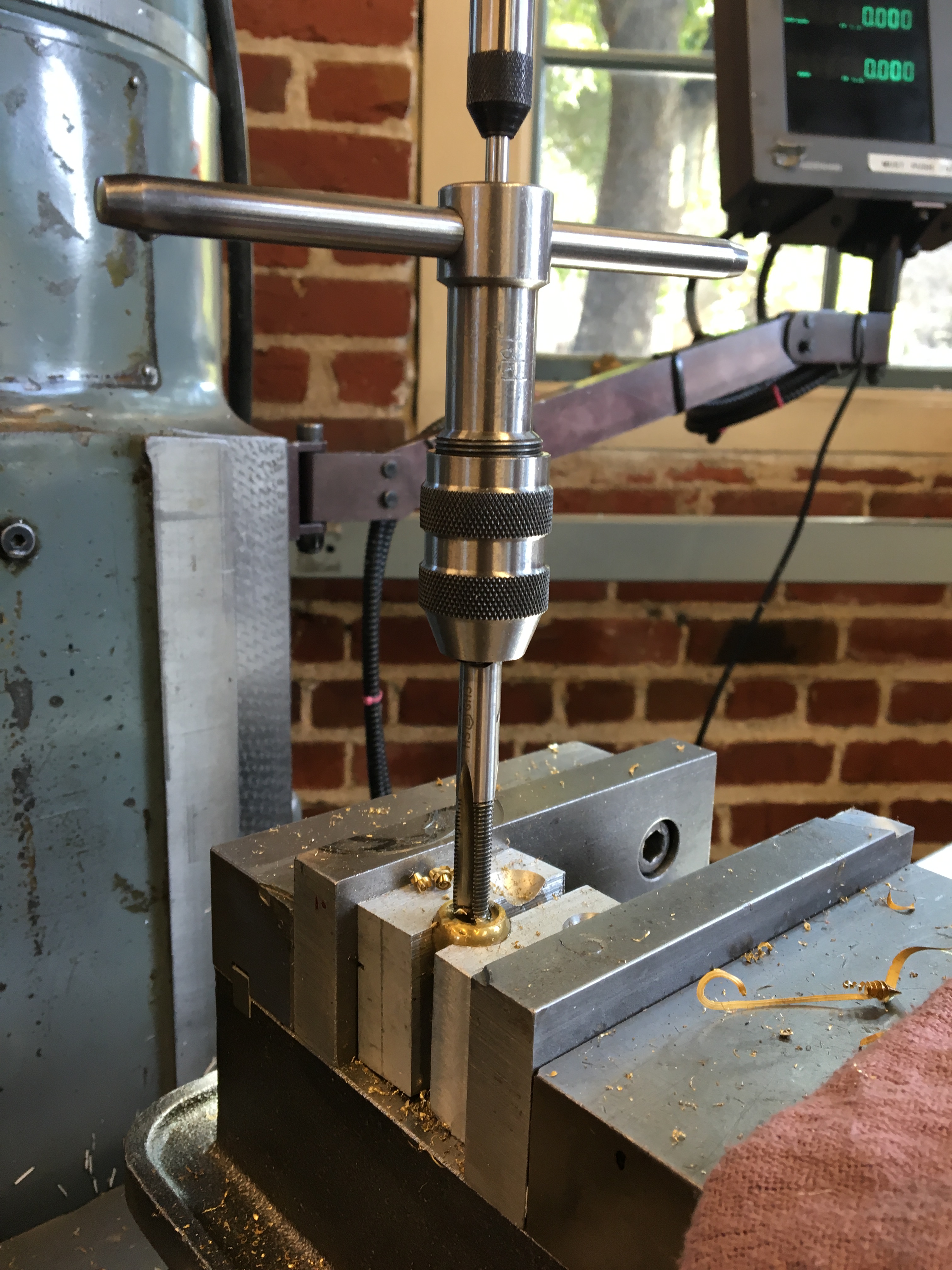
- Tap guide
- T wrench
- Tap
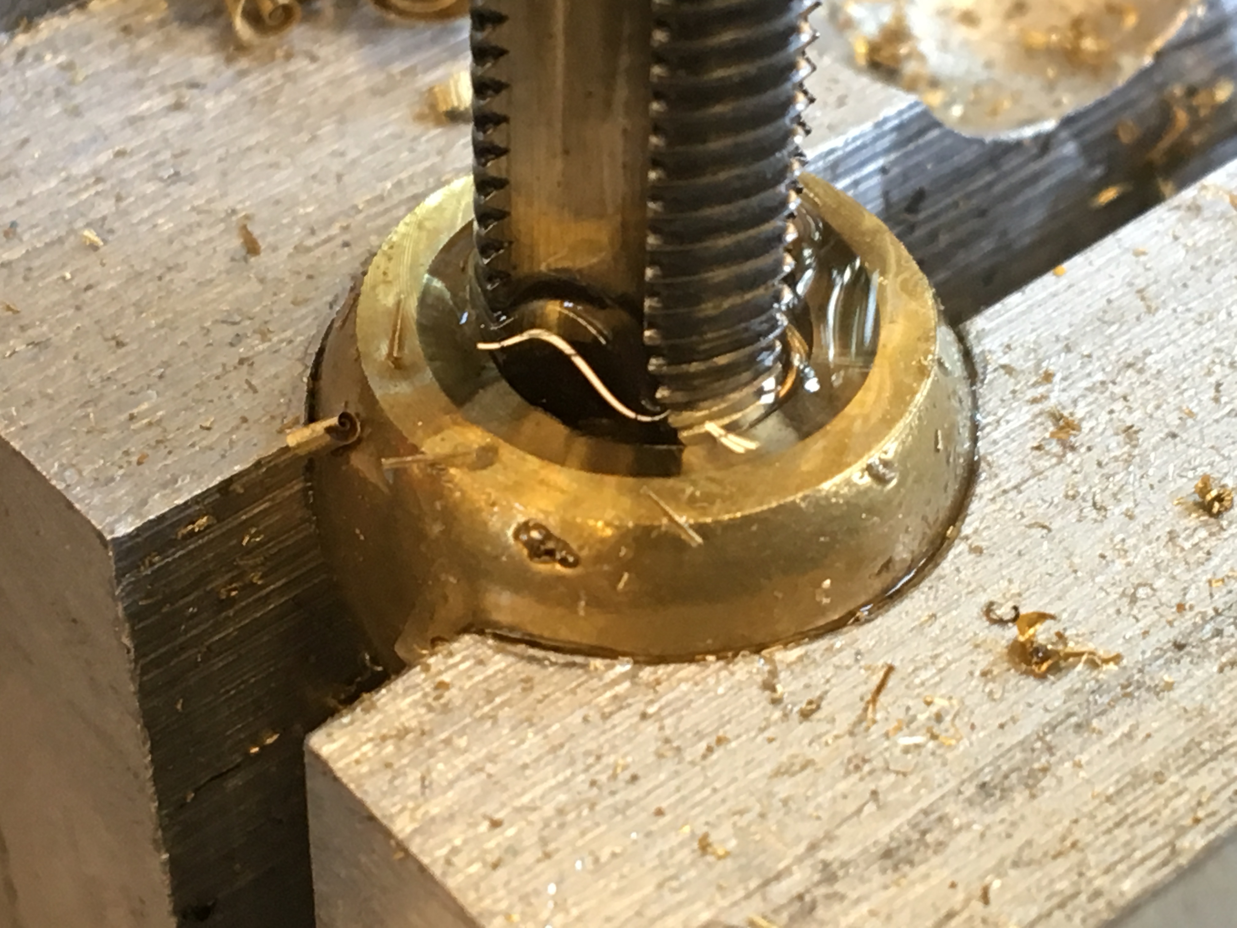
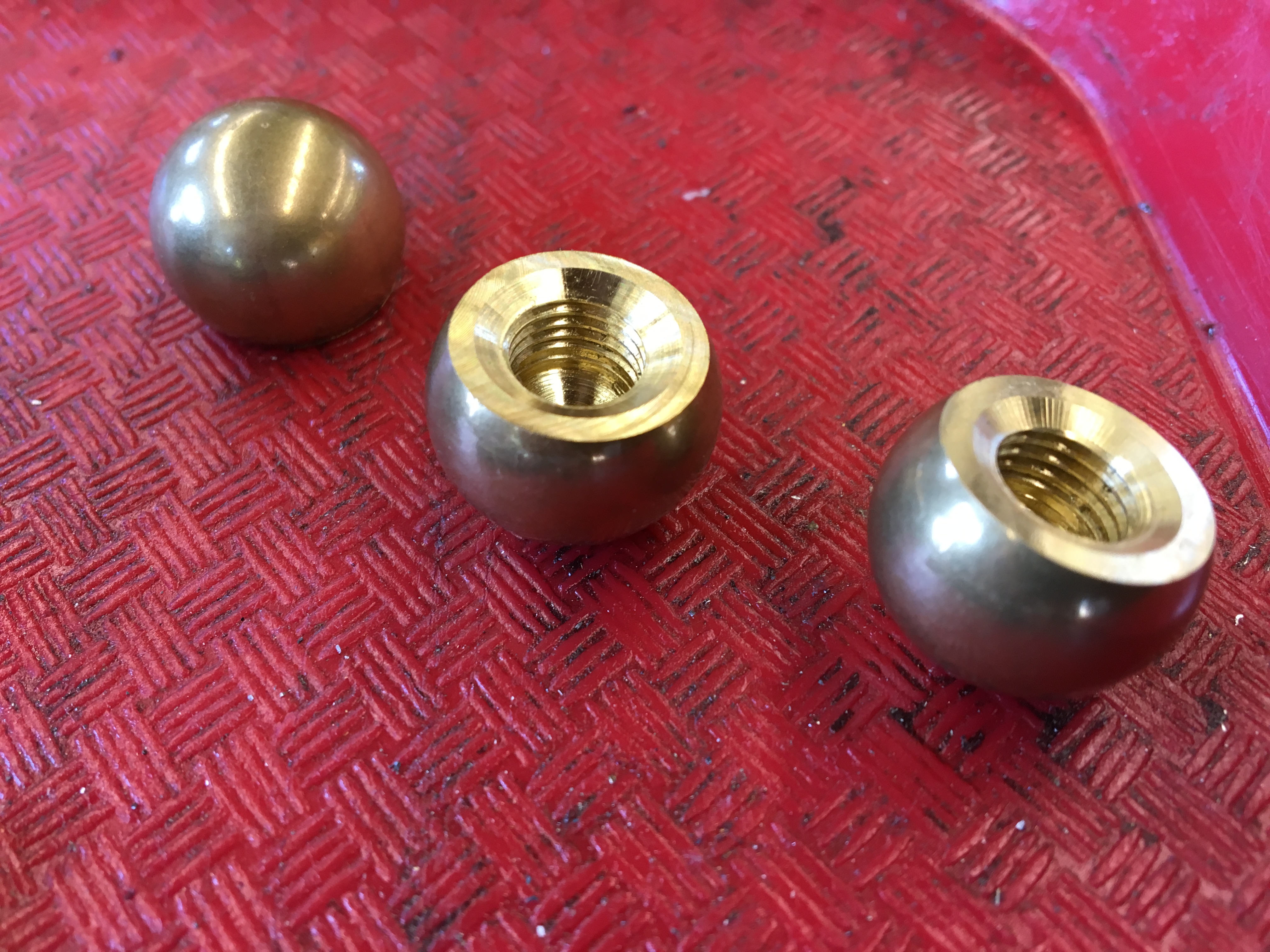
There are actually two taps in the picture: a bottoming tap on the left, and a taper tap on the right. I couldn't drill a very deep hole into the balls otherwise I would have drilled through to the other side, so I needed the bottoming tap to create as many threads as I could in the blind hole.
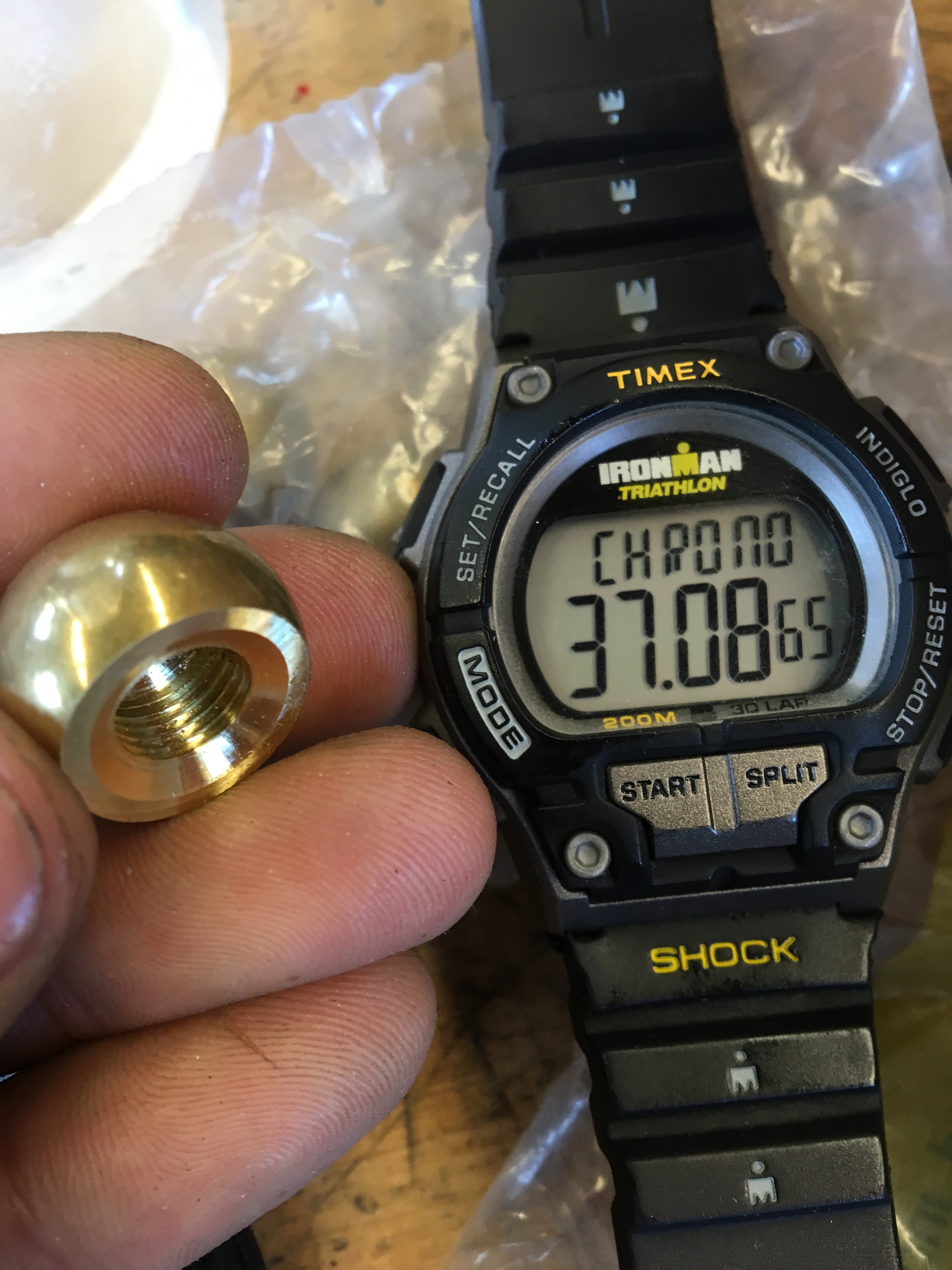
All in all it took ~37 minutes to complete one end cap. After I knew what I was doing I could create one in ~30 minutes. I had to make 10 in all!
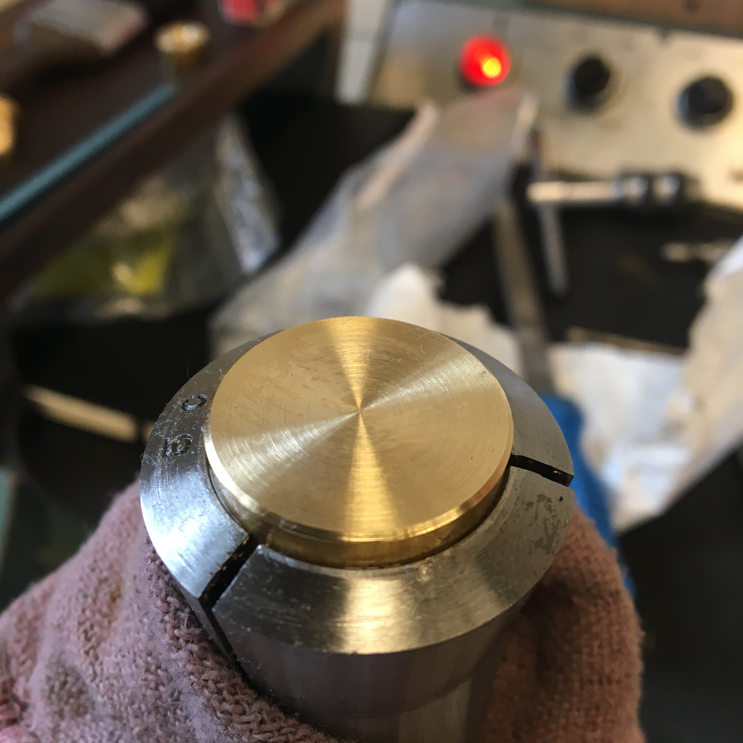
In addition to the ball end caps, I also had to make flat end caps for the feet of the hourglass and the knobs of the axle. I think I also tried to make these on the manual mill, but my custom soft jaws couldn't keep the piece flat, so I ended up going through a similar process on a lathe, which made nice radial surface finishes.
Hourglass
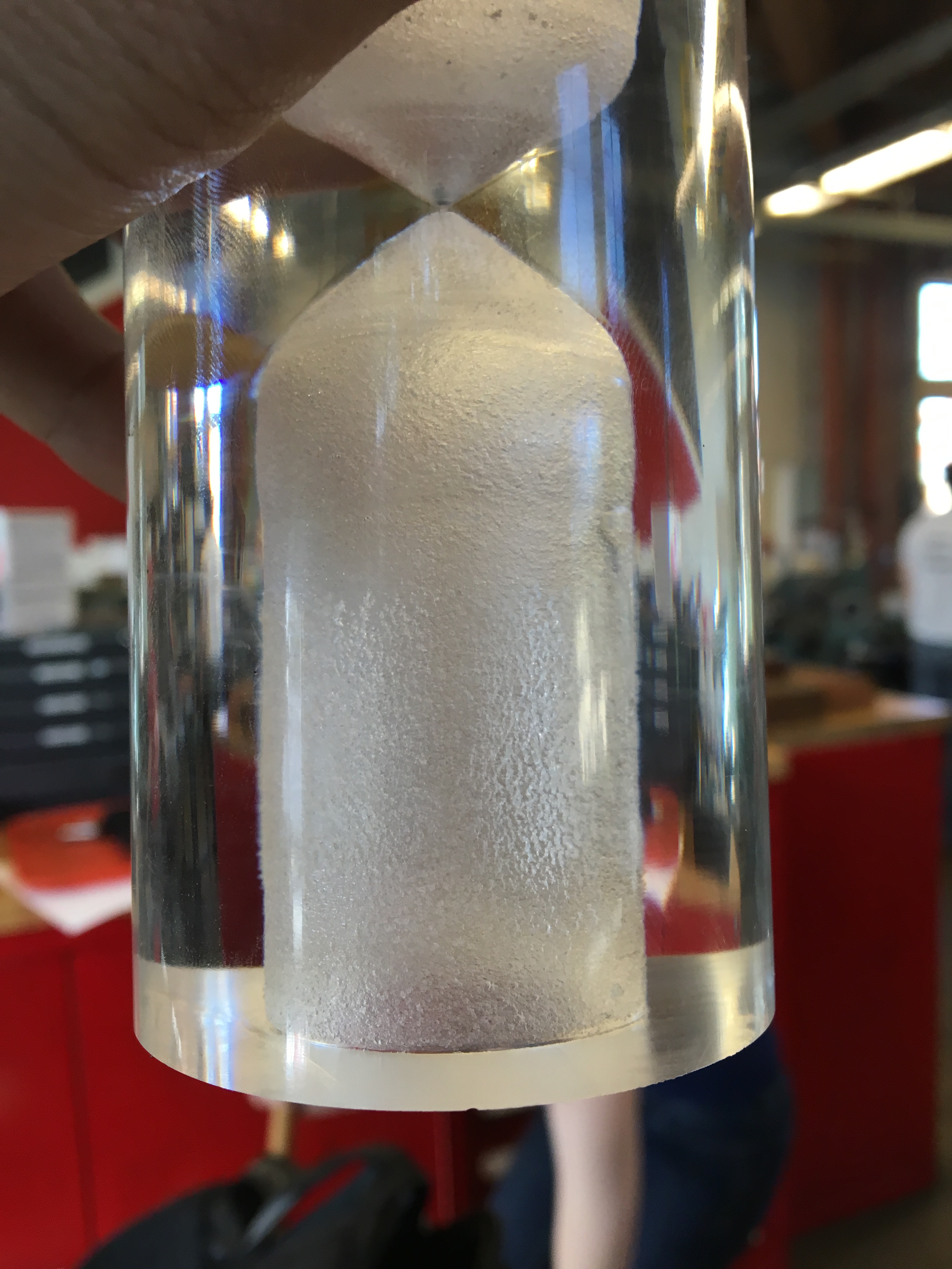
The most of important part of my hourglass was, of course, the actual hourglass itself, machined from a 2 1/2" diameter piece of acrylic.
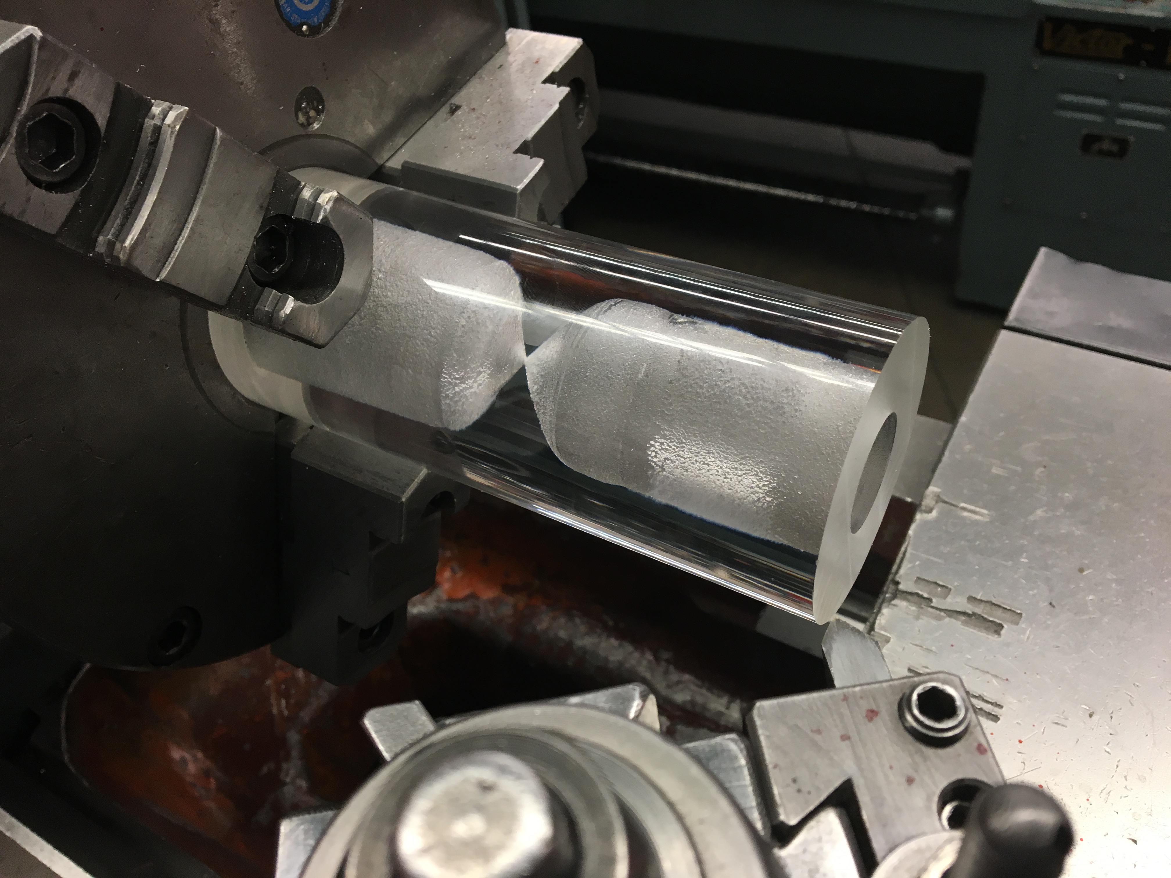
The interior of the hourglass has removed by first drilling holes of increasing diameter, then using a ball end mill and a chamfered end mill to get a smooth curve from the vertical cavity to the small point in the middle. The acrylic didn't respond well to the machining; microfractures occurred just under the machined surface, ruining the clear optics of the hourglass. Later on I put the hourglass on a lathe and stuck sand paper inside to try to remove the microfractures. This was somewhat successful, but small cracks are still visible in the final product, and I was unable to polish the inside to its same original clarity.
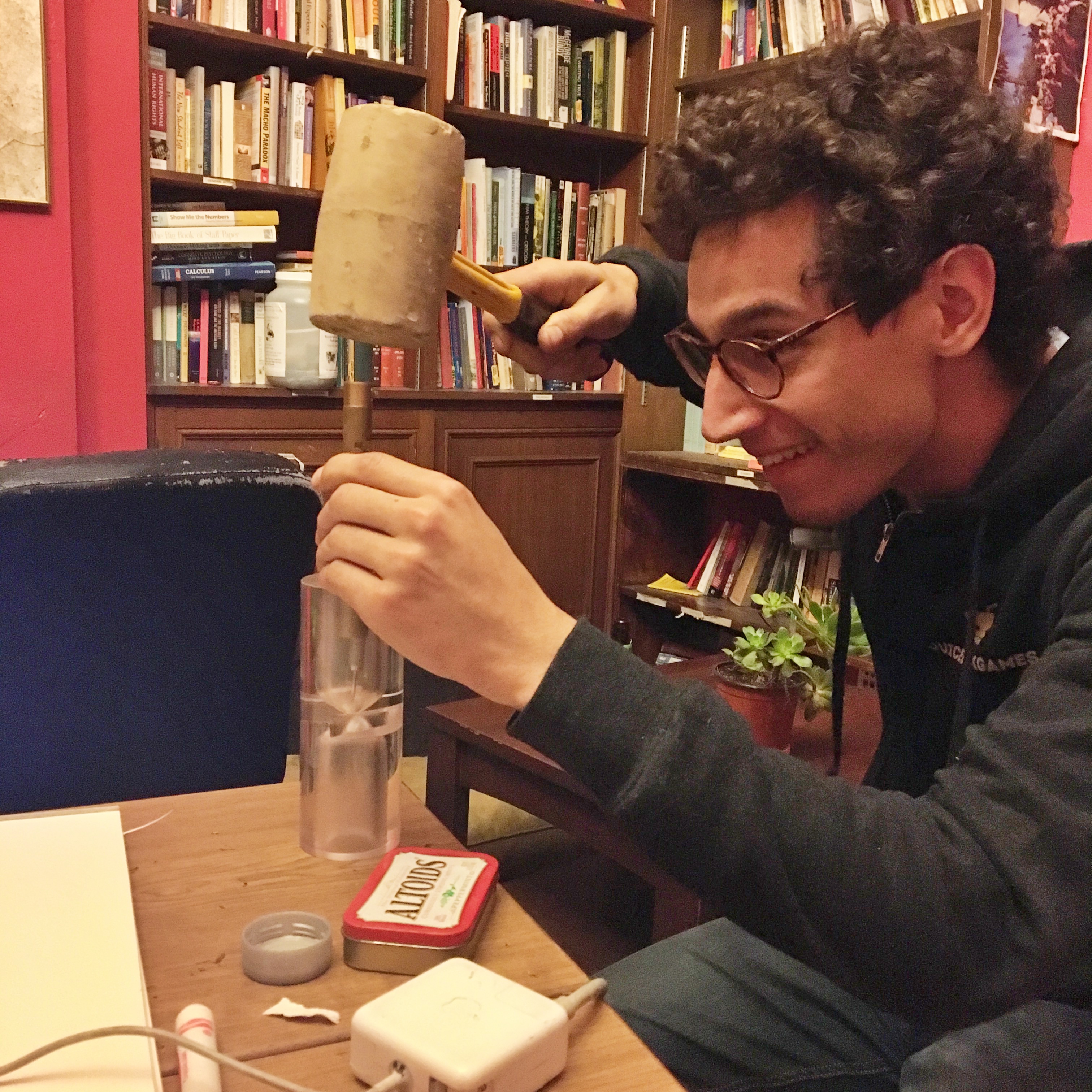
I also didn't have a solid plan for how to create a small hole of the proper diameter at the center of the hourglass. I imagined drilling through with a very small (1/16" or 1/32") drill bit, but no drill bit that small could be mounted in a thin enough chuck that could fit inside the ends of the hourglass. I left this part of the process until the very end, and at the eleventh hour I took off the tip of a dart, dropped it in the hourglass, then put a scrap rod on top and lightly took a mallet to it. After each strike I would take the rod and dart out, then try pouring sand through it. I just used regular beach sand, but if I had gotten finer sand I probably could have ended up with a smaller hole and it would have taken longer for the sand to empty from one side to the other. It only times a couple minutes, and sometimes gets stuck.
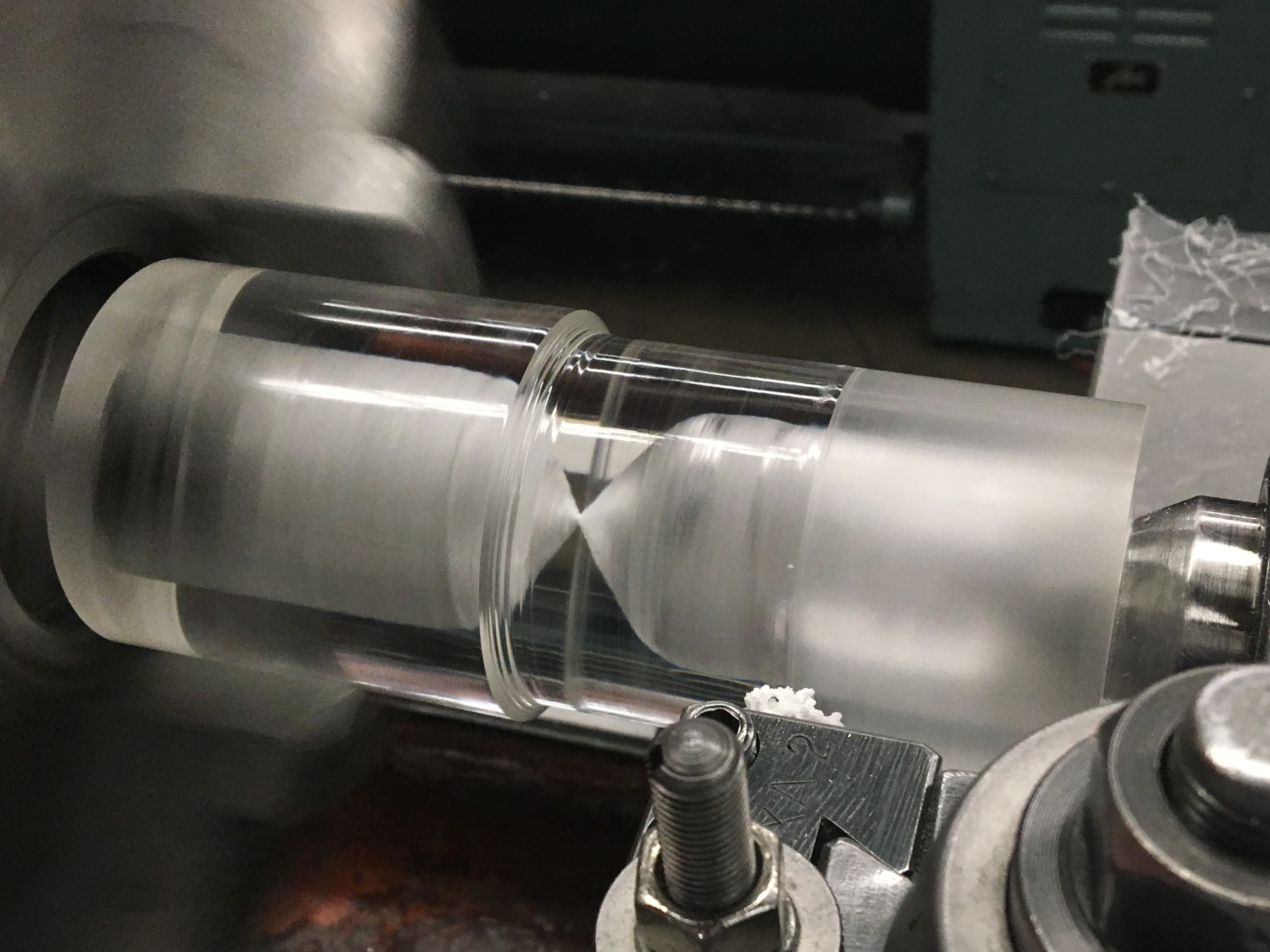
After machining the inside of the hourglass, I had to turn it down to the appropriate diameter. There were some really cool optics when doing this! From the outside the diameter of the inner cavity appears larger than it really is. I would think that how large it appears depends on the outer diameter, but in the second picture below, it looks the same on both sides, even though they have different outside diameters. I never took a physics class on optics, so I don't know what the actual math is here.
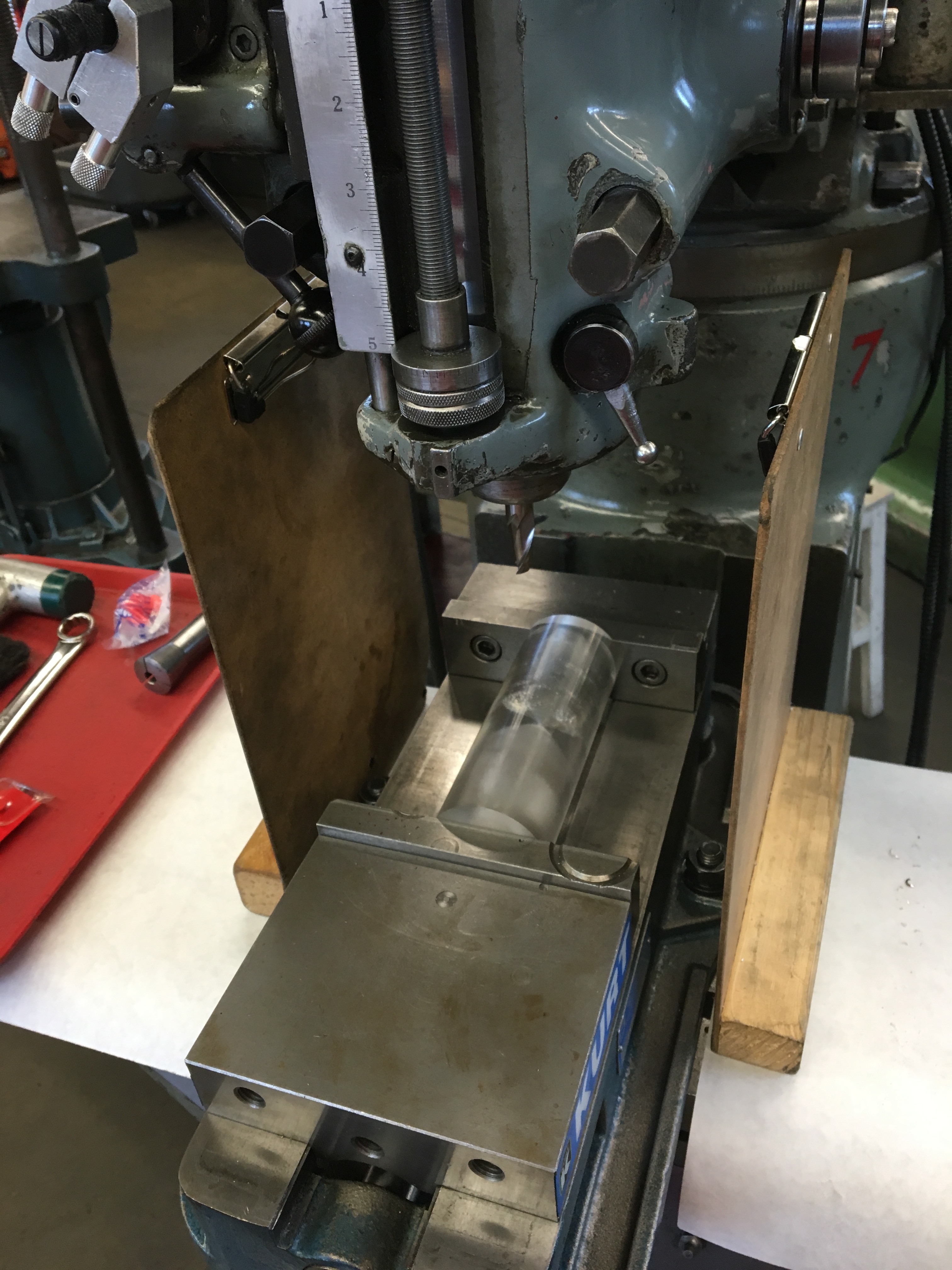
Once the hourglass was turned down to the correct size, I needed to cut out slots for the brass insets. When I drilled the holes I got acrylic chips everywhere, so this time I made to limit how far chips would be thrown. I made sure to test whether the brass insets (next section) fit before I unmounted everything.
Brass Insets
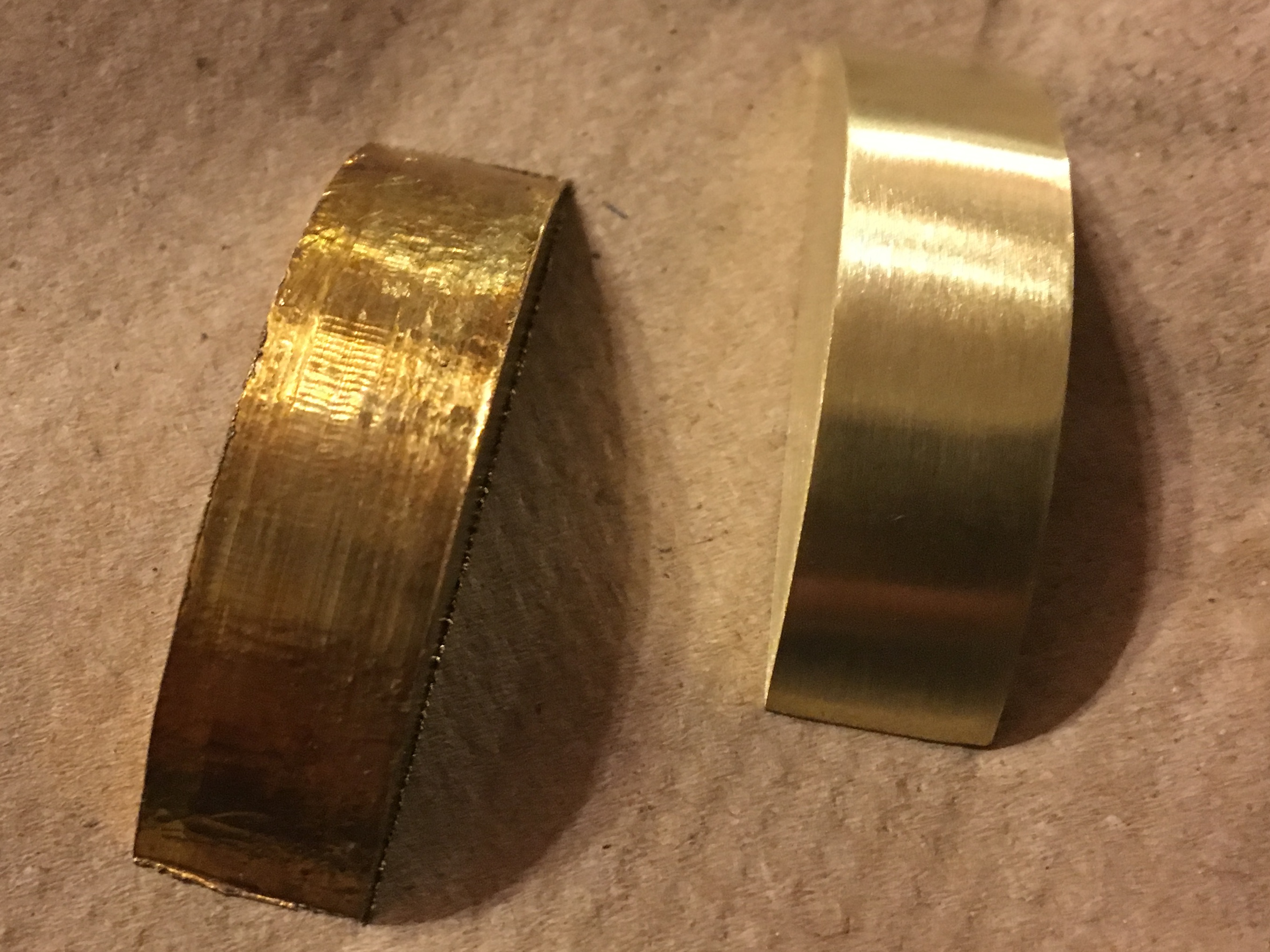
I created the brass inset pieces from a plate of brass and machining it on a rotary table. I'm not sure this was the most efficient was to create these pieces. I clamped the slab on top of a piece of sacrificial material and first machined out a disk. While doing this the slab got super hot and the sacrificial material almost melted to the slab. After I had the disk, I cut that in two and then faced down the two halves to the appropriate height.
I think the extreme heat when cutting out the disk contributed to a particularly poor surface finish and very rough edges. The difference before and after sanding was like night and day:
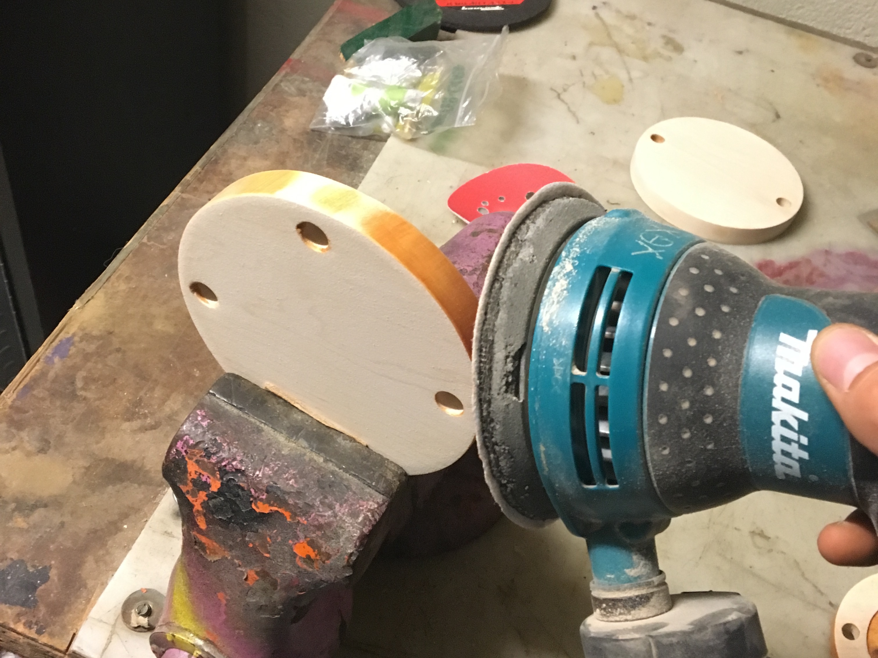
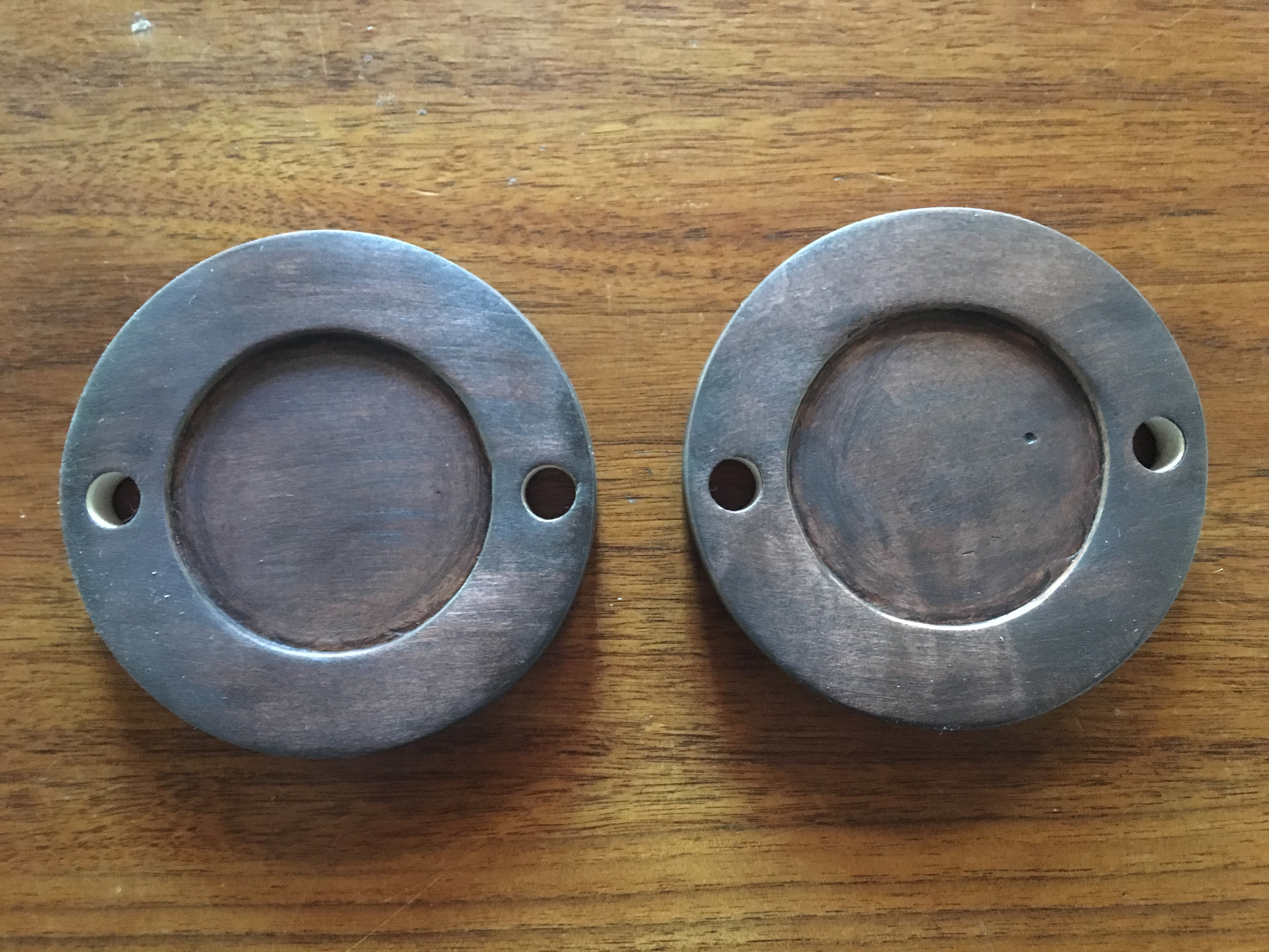
Wood Stand Caps
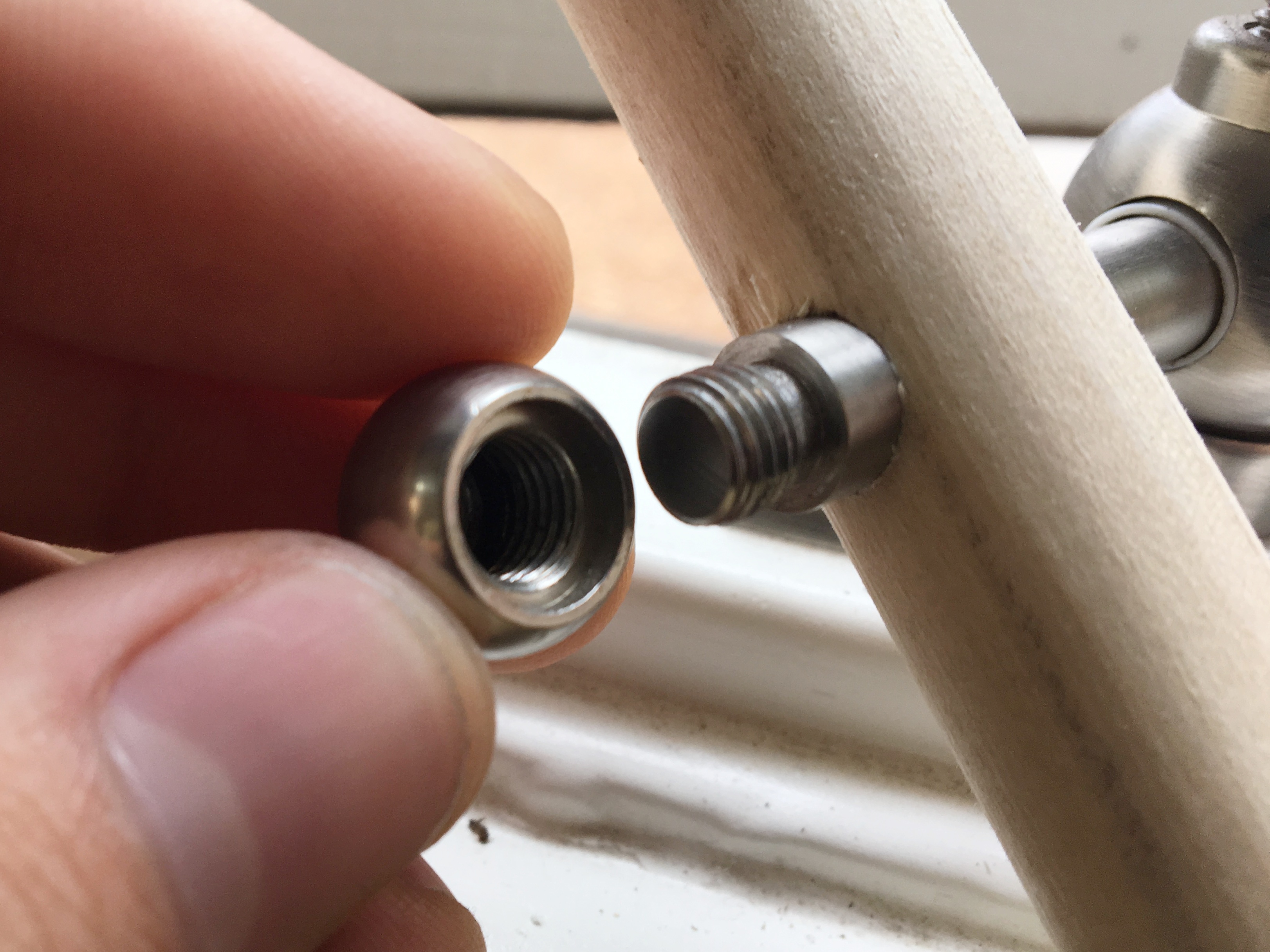
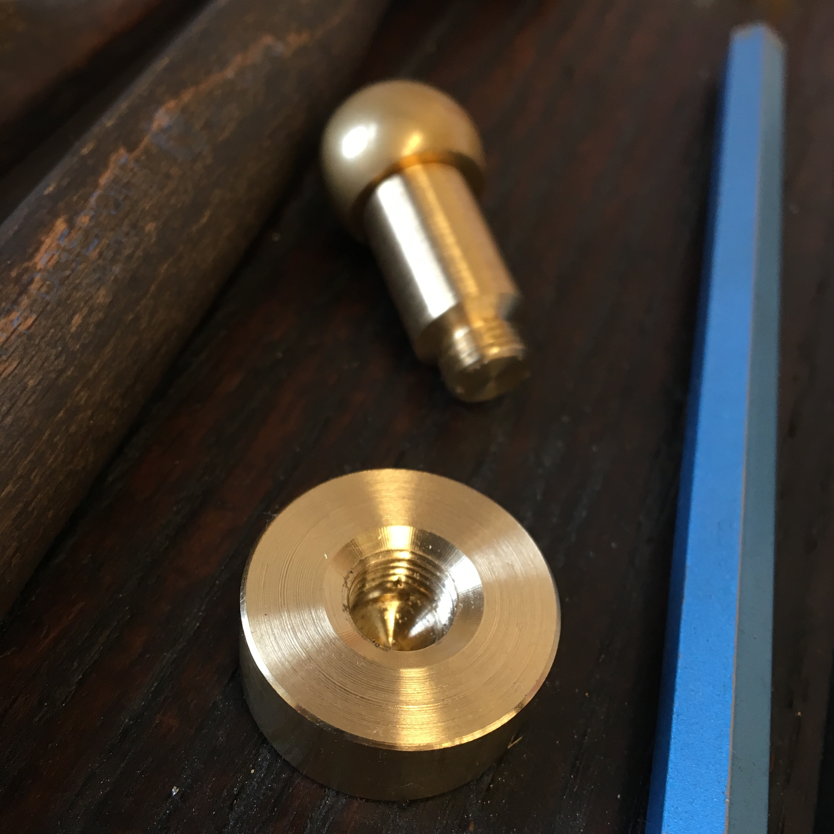
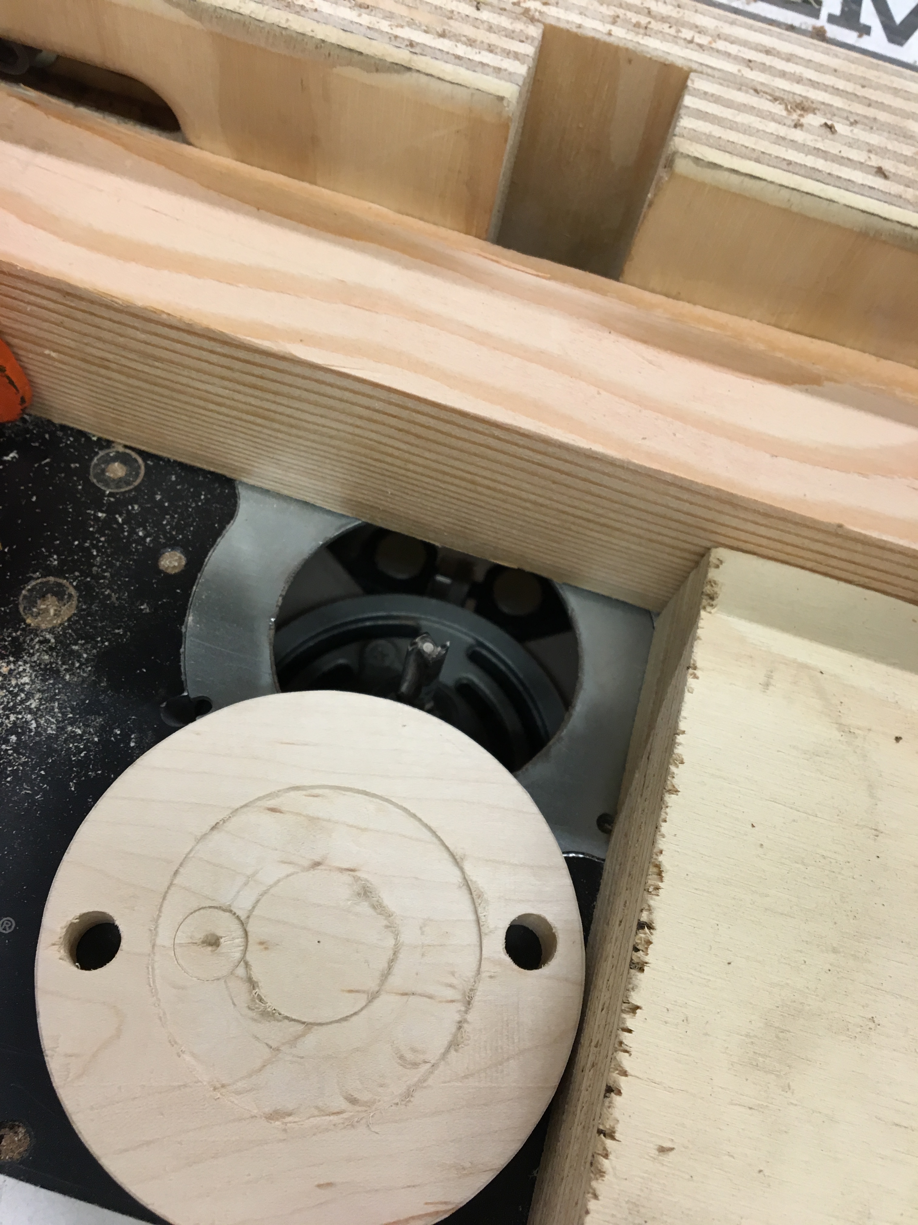
I cut the circles out of a simple board with a band saw, and drilled the holes for the supports with a drill press. When I tested screwing the support through the cap there was a gap between the wooden cap and the bottom of the ball cap, which I had to resolve by trimming off a couple threads from the end of the support.
I used a table router to carve out the pockets on the inner caps for the the hourglass to sit in.
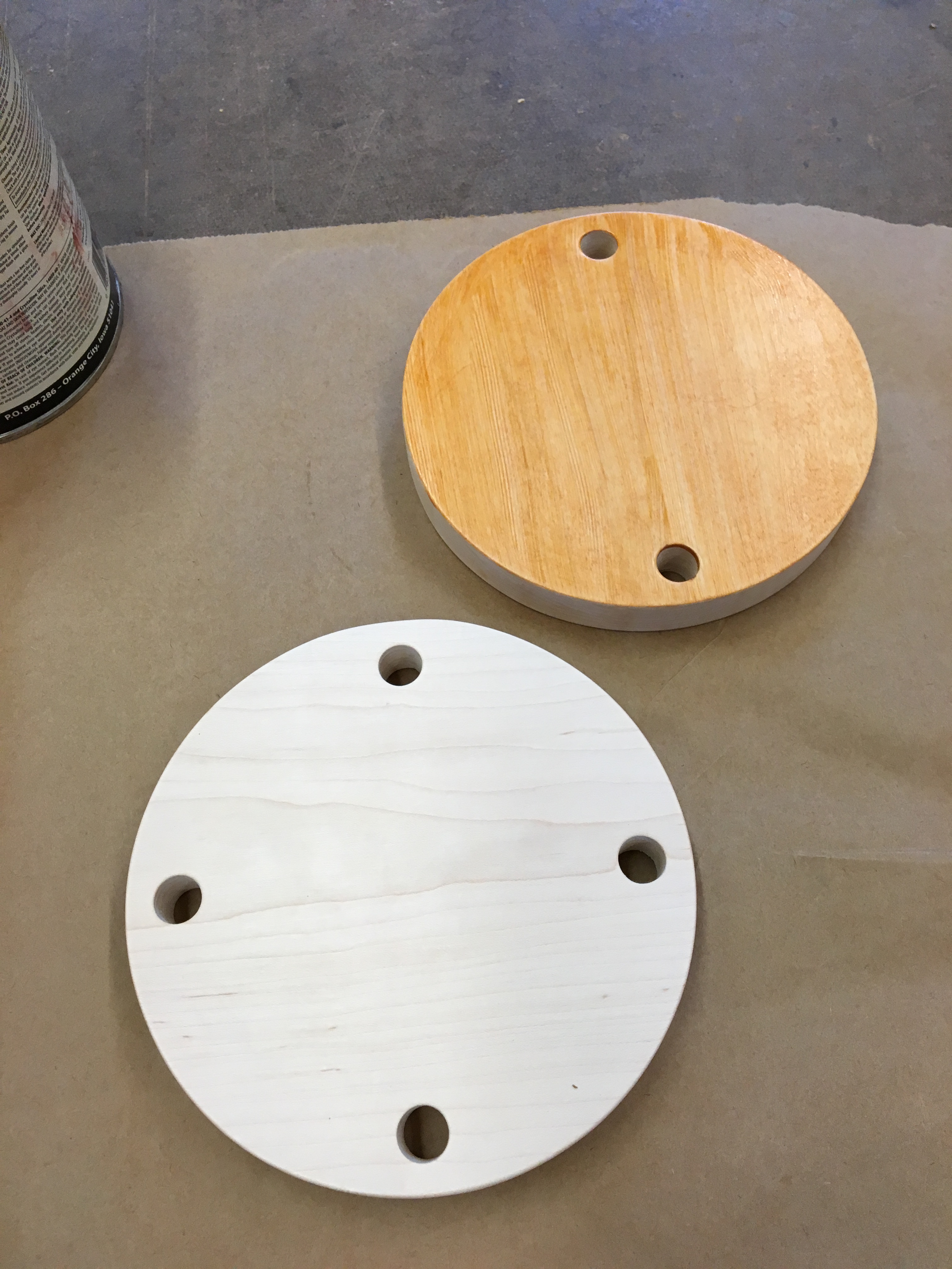
I was running out of time at the end of the quarter and used the best wood stain I could find in the woodshop. This was a super ugly orange color. Luckily I came to my sense and made the trip to a hardware store for a much better brown stain.
Assembly
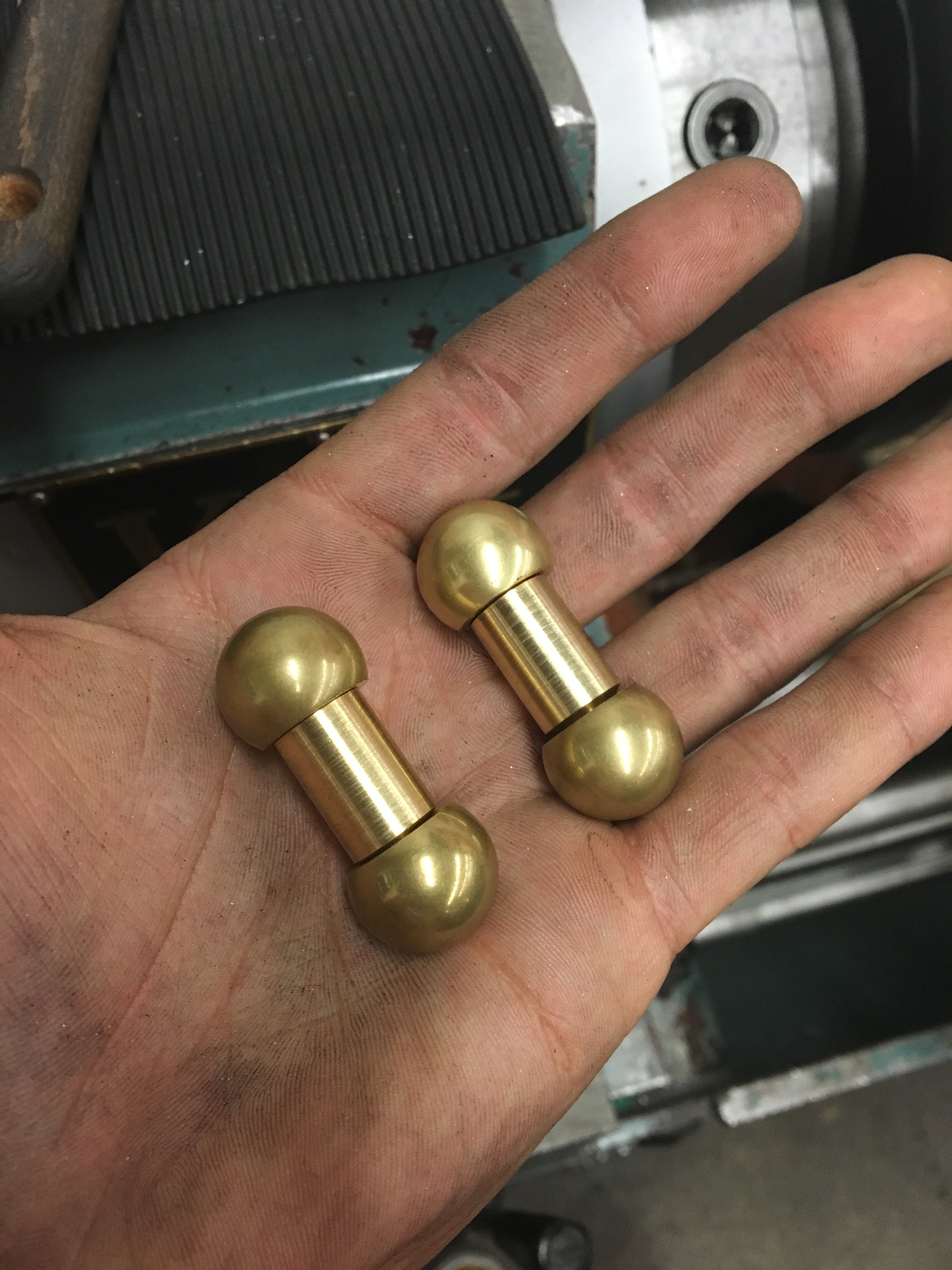
Before putting everything together I put the support stands and end caps on a lathe for final sanding. They came out looking incredible.
32 parts in total! (The axles have already been press fit into the insets which is why there are only 30 distinct pieces in the image.)